
A4 Mk2
| Removing gearbox - vehicles with 2.0 ltr. TFSI engine |
| Special tools and workshop equipment required |
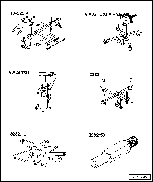
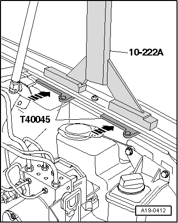
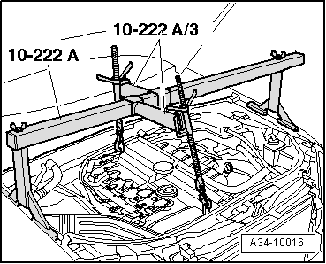
| t | Support bracket -10-222 A- |
| t | Engine and gearbox jack -V.A.G 1383 A- |
| t | Used oil collection and extraction unit -V.A.G 1782- |
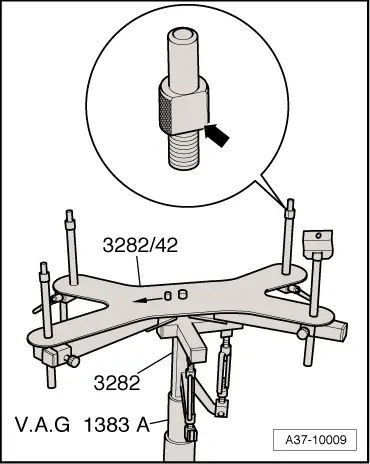
| t | Gearbox support -3282- |
| t | Adjustment plate -3282/48- |
| t | Pin -3282/50- |
|
|
|
|
 Note
Note
|
|
 Caution
|
|
|
|
|
|
|
|
|
|
|
|
|
|
|
|
|
|
Note |
|
|
|
|
|
|
|
Note
Note
|
|
Note |
|
|
|
|
|
|
|
|
|
Note
|
|
|
|
|
|
Note
|
|
|
|
|
|
|
|
Note
|
|
|
|