audi Workshop Repair Guides

Audi Workshop Service and Repair Manuals

Renewing grooved ball bearing for input shaft with gearbox removed (gearbox remains assembled) > < Dismantling gearbox
Assembling gearbox
Assembling gearbox
If the gearbox housing or the final drive gear set have been renewed, you must first re-determine the thickness of the shim “S6 → Chapter. The shim is located on the pinion shaft and is responsible for the proper positioning of the 2nd speed selector gear.
Re-determine thickness of shim(s) “S5” if final drive gear set is being renewed → Chapter. The shim is located on the pinion shaft and is responsible for the proper positioning of the 4th gear wheel.
Always renew the double angular contact ball bearing on the pinion shaft when renewing the final drive gear set or if gear oil is contaminated with metal particles.
  Note
t  Carefully use thread tap to remove any remaining locking fluid from all threaded holes which will accommodate self-locking bolts.
t  Clean the thread for the nut on the pinion shaft.
t  Lubricate all needle bearings and synchro-rings with gear oil before fitting.
t  Thoroughly clean housing joint surfaces.
t  Check synchro-rings for wear → Fig..
t  Heat needle bearing inner races, gear wheels and roller bearings to 100 °C (max.) before pressing on.
  WARNING
Wear protective gloves when positioning heated components.
–  Fit shim “S3” in gearbox housing.
   
–  Lubricate outer races -3- and -4- with gear oil.
–  Carefully push pinion shaft -1- with double angular contact ball bearing into gearbox housing -2- by hand (press down top outer race -3-).
  Note
Using hot air blower, heat area around seat of bearing in gearbox housing if necessary.
Make sure that outer races -3- and -4- are kept straight when inserting and that they remain attached to each other. Otherwise the seal -6- can be damaged by the pinion gear -5-.
The bearing must be renewed if the seal of the double angular contact ball bearing is damaged.
  A34-10237
–  Fit shim “S4” and retaining plate -A- (can only be fitted in one position).
–  Clean threads of old bolts -arrows- with a wire brush. Then insert bolts with locking fluid -AMV 185 101 A1- and tighten to 30 Nm in diagonal sequence.
–  Install differential → Chapter.
l  Now re-determine thickness of shim “S5 → Chapter if pinion shaft (final drive gear set) is being renewed.
  A34-10236
–  Fit shim(s) “S5-arrow- onto pinion shaft.
  A34-10235
Driving on 4th gear wheel as far as stop.
t  Installation position:
High inside collar faces 3rd gear.
l  Shoulder of press tool -3118- and tube -VW 415 A- faces towards 4th gear wheel.
  A34-10238
–  Make sure that 3rd gear wheel -1- meshes with 3rd speed selector gear -2- on input shaft.
t  Installation position of 3rd gear wheel:
High inside collar faces 4th gear.
–  Now insert input shaft together with selector forks -3- and -4- into gearbox housing in direction of -arrow-; fit 3rd gear wheel onto pinion shaft when doing so.
  A34-10239
Driving on 3rd gear wheel as far as stop.
  A34-10240
Driving on 6th gear wheel as far as stop.
t  Installation position:
High inside collar faces 5th gear.
  A34-10241
Driving on 5th gear wheel as far as stop.
t  Installation position:
High inside collar faces 6th gear.
  A34-10242
Driving on roller bearing -A- for pinion shaft.
If gearbox housing, final drive gear set or gear wheels on pinion shaft are being renewed, you must now re-determine shim “S6” for positioning 2nd speed selector gear → Chapter.
  A34-10243
–  Fit bearing mounting -A-.
The mounting -B- for reverse shaft must be fitted on the bearing mounting.
  A34-10244
Driving on needle bearing inner race -A- for 2nd speed selector gear
l  First fit shim “S6-B-.
  A34-10245
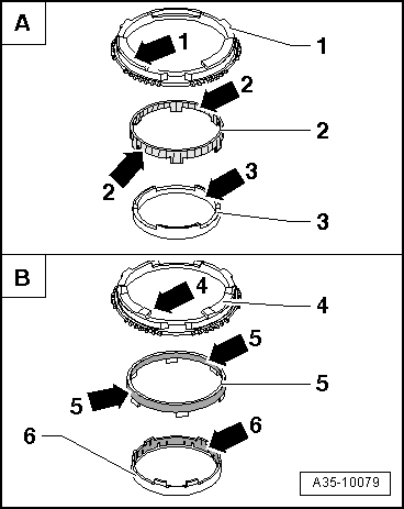
Checking synchro-rings for 1st, 2nd and reverse gear for wear
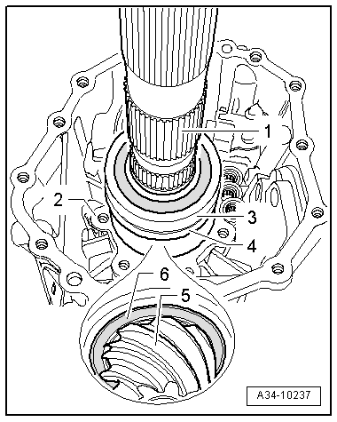
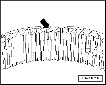
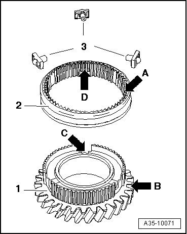
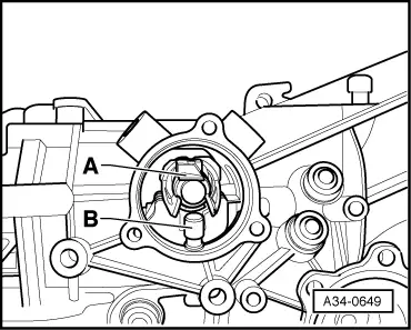
–  Check outer friction surface on inner ring for scoring or visible traces of wear and renew if necessary.
–  Check inner friction surface of synchro-ring for scoring or visible traces of wear and renew if necessary.
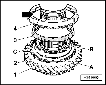
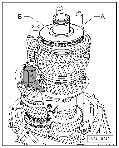
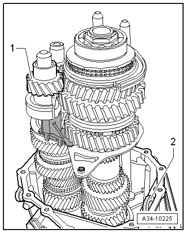
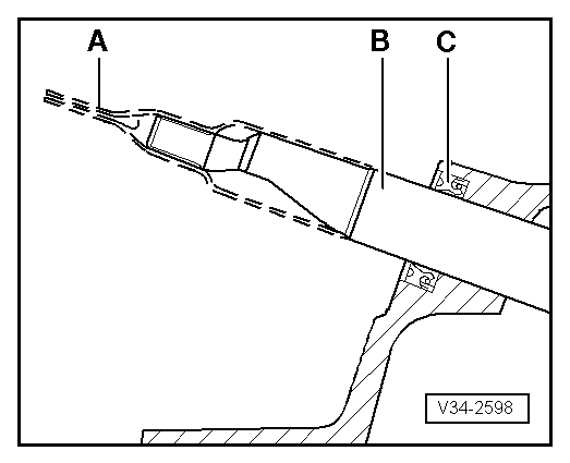
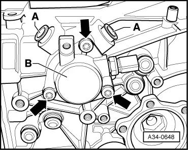
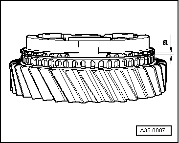
–  Fit inner ring, intermediate ring and synchro-ring onto cone of selector gear/clutch unit and rotate rings to achieve proper seating.
  Note
To achieve proper seating, rotate synchro-rings approx. one turn while pressing down rings simultaneously.
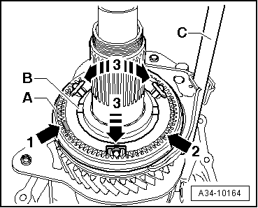
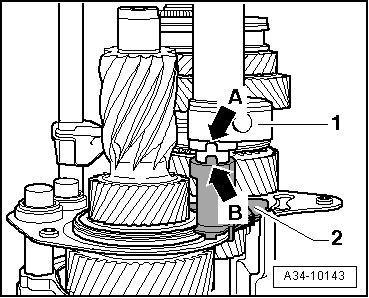
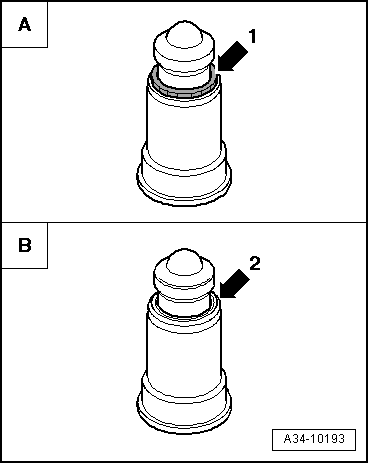
–  Then measure gap -a- using a feeler gauge.
  A35-0087
Gap -a-Wear limit
1st and 2nd gear0.7 mm
Reverse gear0.7 mm

  Note
Renew inner ring, intermediate ring and synchro-ring for the corresponding gear together.
   
Identification of reverse gear synchro-rings -A- and 1st/2nd gear synchro-rings -B-
1 - Reverse gear synchro ring: the lugs -arrow 1- have a smooth surface.
2 - Reverse gear intermediate ring: the friction surfaces -arrows 2- are coated with sintered particles (brass colour).
3 - Reverse gear inner ring: has no inner friction surface -arrow 3-.
4 - Synchro-ring for 1st and 2nd gear: the lugs are fitted with 2 projections each -arrow 4-.
5 - Intermediate ring for 1st and 2nd gear: the friction surfaces -arrows 5- are carbon-coated (black coating).
6 - Inner ring for 1st and 2nd gear: the inner friction surface -arrow 6- is carbon-coated (black coating).
  Note
Do not interchange synchro-ring for 1st gear (item 4) with synchro-ring for 2nd gear. The synchro-ring for 2nd gear has asymmetric splines, which are matched to the locking collar → Anchor.
  A35-10079
Installation position of synchro-rings for 1st, 2nd and reverse gear
  Note
t  If components are not being renewed, make sure they are re-installed on the same gear.
t  Do not interchange synchro-rings for reverse gear with synchro-rings for 1st and 2nd gear → Fig..
–  Fit inner ring -2- onto selector gear -1-/clutch unit.
–  Fit intermediate ring -3-. Lug -B- must be inserted into recess -A-.
–  Fit synchro-ring -4-. Guide lugs -C- through recess -arrow-.
–  Place 2nd speed selector gear with needle bearing and synchro-rings onto pinion shaft.
–  Then fit synchronising hub for 1st and 2nd gear.
  A35-0093
Note correct position of locking collar for 1st and 2nd gears. The side with asymmetric splines -arrow- must point towards 2nd gear.
  A34-10216
–  Fit locking collar -A- (in installation position) together with selector fork for 1st and 2nd gear -C- over synchronising hub -B-.
  Note
The locking collar can only be fitted over the synchronising hub in one position; the gaps in the splines -arrow 1- and -arrow 2- have different widths. Detach synchronising hub -B- from pinion shaft and turn upside down if necessary.
–  Then position thrust blocks in recesses in synchronising hub and press thrust blocks in direction of -arrow 3- into recesses in locking collar. The locking collar must be held in the centre position.
  A34-10164
Driving on needle bearing inner race -1- for 1st speed selector gear.
–  Place 1st speed selector gear with needle bearing and synchro-rings onto needle bearing inner race.
  A34-10246
Driving on thrust washer -A- for 1st gear and reverse gear and needle bearing inner race -B- for reverse selector gear
  A34-10247
Assembling locking collar and reverse selector gear
1 - Reverse selector gear
2 - Locking collar
3 - Thrust blocks
–  Push locking collar over reverse selector gear.
Installation position:
l  After assembling, the pointed splines -arrow A- on the locking collar point away from the driving teeth -arrow B- of the reverse selector gear.
l  Recesses for thrust blocks -3- in reverse selector gear -arrow C- and locking collar -arrow D- must align.
–  Then position thrust blocks in recesses on reverse selector gear and press thrust blocks into recesses in locking collar.
  A35-10071
–  Fit reverse selector gear -1- (with locking collar fitted) together with needle bearing and reverse gear selector rod -2-.
  A34-10248
–  Fit clutch unit -A- with reverse gear synchro-rings.
–  Fit washer -B- onto clutch unit.
–  Heat grooved ball bearing for pinion shaft to max. 130 °C.
  A34-10249
Driving on grooved ball bearing
  A34-10250
–  Move selector rods to neutral -arrow-.
–  Drive in locking bushes -1- to -4- for selector rods as far as stop using tube -VW 421-.
1 - Locking bush for reverse gear selector rod
2 - Locking bush for 1st and 2nd gear selector rod
3 - Locking bush for 5th and 6th gear selector rod
4 - Locking bush for 3rd and 4th gear selector rod
  Note
Do not interchange locking bushes for selector rods and selector shaft.
  A34-10144
–  Secure adapter -T10235- in tapped hole on right side of gearbox housing using a bolt M10 x 70 -A- as shown on illustration.
–  Secure support plate -T10108/1- to flange shaft (right-side) with 2 bolts M10 x 35 -B-. When doing this, insert 2 nuts nut M12 -C- between flange shaft and support plate.
–  Turn gearbox in assembly stand so that it is in horizontal position.
  A34-10251
–  Secure adapter -T10235- in tapped hole on left side of gearbox housing using a bolt M10 x 70 -A- as shown on illustration.
–  Secure support plate -3221/1A- to flange shaft (left-side) with 2 bolts M10 x 35 -B-. When doing this, place a nut M12 and washer -C- on each bolt between flange shaft and gearbox support.
l  The support plates must rest against the adapters -T10235-.
l  The shoulder -arrow- of support plate -3221/1A- should face gearbox housing.
l  The gearbox must be in neutral.
–  Support pinion shaft with engine and gearbox jack -V.A.G 1383 A- and universal gearbox support -V.A.G 1359/2-. When doing so, position plate -2004/1- below grooved ball bearing on pinion shaft.
–  Clean thread of pinion nut. Then apply locking fluid -AMV 185 101 A1- to nut and tighten to 300 Nm.
D - Socket attachment (46 mm) with 3/4" drive.
E - Torque wrench
–  Then check selector gears for freedom of movement and axial play.
l  The axial play of the selector gears must be at least 0.10 mm.
–  Position gearbox vertically in assembly stand.
  A34-10252
–  Fit reverse shaft -1- with recess -arrow A- onto lug -arrow B- of reverse shaft mounting -2-.
  A34-10143
–  Fit reverse gear wheel -1- with needle bearing onto reverse shaft; teeth of reverse gear wheel must point towards reverse selector gear.
–  Fit magnet -2- into rib in gearbox housing.
–  Check whether the two dowel sleeves for centring gearbox cover to gearbox housing are fitted in gearbox cover.
–  Apply sealing paste -AMV 188 001 02- evenly and not too thickly onto contact surfaces between gearbox housing and gearbox cover.
Assembly sequence for gearbox cover:
  A34-10225
–  Fit gearbox cover -B- onto gearbox housing. Do not screw in bolts -A- at this stage.
–  Screw in bolt -arrow 2- into reverse shaft hand-tight.
–  Screw new bolts -arrows 1- into bearing mounting and tighten hand-tight.
–  Then tighten the 13 bolts -A- to 24 Nm.
–  Then tighten bolts -arrows 1- to 27 Nm and bolt -arrow 2- to 24 Nm.
–  Then turn gearbox in assembly stand in horizontal position.
  A34-10223
–  Then install circlip -arrow- in front of grooved ball bearing for input shaft.
  Note
If necessary, pull input shaft out of gearbox housing as far as stop by hand so that the circlip can be fitted properly.
  A34-10127
–  Lubricate new O-ring -arrow- with gear oil before fitting into circumferential groove on gearbox housing.
–  Fit a thin insulating hose or shrink hose onto input shaft splines.
–  Pack space between sealing lip and dust lip of oil seal in guide sleeve half-full with sealing grease -G 052 128 A1-.
–  Lightly oil outer circumference of guide sleeve.
  A30-0116
–  Push guide sleeve -2- over input shaft and into gearbox housing.
–  Remove insulating hose/shrink hose.
–  Fit retaining piece -1-.
1.  Clean threads of bolts -arrows- with a wire brush. Then insert bolts with locking fluid -AMV 185 101 A1- and tighten to 24 Nm.
–  Insert intermediate piece -3- in gearbox housing.
  A34-10197
Only on Audi A4 and Audi Cabriolet:
–  Before installing clutch release lever -3-, apply a thin coat of copper grease to contact surface for operating rod of clutch slave cylinder.
Continued for all models:
–  Install clutch release lever together with release bearing.
–  Clean thread of bolt -1- with a wire brush.
–  Position leaf spring -2- onto bolt -1-.
–  Then insert bolt -1- with locking fluid -AMV 185 101 A1- and tighten to 24 Nm.
  A30-0112
–  Push assembly sleeve -01E 311 120--A- onto selector shaft -B-.
  Note
To avoid damaging oil seal -C-, oil seal and selector shaft must only be fitted using assembly sleeve -01E 311 120--A-.
l  Selector rods must be in neutral position.
–  Install complete selector shaft.
l  Installation position: Chamfer of selector shaft points downwards.
  V34-2598
–  Push selector shaft -A- into gearbox as far as it will go, simultaneously inserting pin -B-.
l  Use pin without lug → Item when renewing gearbox housing.
l  Installation position of pin -B- with lug: insert end with lug into gearbox housing.
l  Installation position of pin -B- without lug: pin is fitted in gearbox housing without radial clearance.
  A34-0649
–  Fit cover -B- with new O-ring.
–  Clean threads of bolts -arrows- with a wire brush. Then insert bolts with locking fluid -AMV 185 101 A1- and tighten to 24 Nm.
A - Locking bushes for selector shaft
  Note
  A34-0648
t  Install only version -B- of locking bushes for selector shaft with flanged edge -arrow 2-.
t  If the gearbox is fitted with selector shaft locking bushes of type -A-, these must always be replaced with locking bushes of type -B-. Parts No. → Electronic parts catalogue “ETKA”.
t  Version -B- can be re-used if already installed.
  A34-10193
–  Drive in selector shaft locking bushes → Anchor using tube -VW 421-.
–  Select all gears.
  A34-0653

Renewing grooved ball bearing for input shaft with gearbox removed (gearbox remains assembled) > < Dismantling gearbox