audi Workshop Repair Guides

Audi Workshop Service and Repair Manuals

Pinion shaft and hollow shaft > < Input shaft - exploded view
Dismantling and assembling input shaft - assembly sequence
   
Dismantling and assembling input shaft - assembly sequence
Special tools and workshop equipment required
t  Thrust plate -VW 401-
t  Thrust plate -VW 402-
t  Press tool -VW 412-
t  Tube -VW 415 A-
t  Drift sleeve -30 - 100-
t  Tube -32 - 109-

   
t  Drift sleeve -40 - 21-
t  Tube -2040-
t  Guide sleeve -3039-
t  Tube for wheel bearing -3345-
t  Thrust plate -T10084 A-
t  Feeler gauge

   
t  Clamping device -T10306-
  W00-10328
t  Angled ring spanner -T10307-
Dismantling input shaft
–  First remove circlip → Item and washer → Item in front of 12-point nut on removed input shaft.
  W00-10329
–  Apply angled ring spanner -T10307- to 12-point nut.
–  For the next step, the end of the input shaft with the clutch plate splines must be placed in clamping device -T10306- and clamped in a vice.
A - Torque wrench
  Note
t  Due to the offset centre of gravity of the input shaft, the input shaft must be supported (e.g. by a second mechanic).
t  The 12-point nut has a “left-hand thread” (turn tool clockwise to unfasten nut).
–  Unfasten twelve-point nut by turning in direction of -arrow-.
–  Remove 4th speed selector gear with needle bearing and synchro-rings.
  A35-10067
–  Press off 3rd speed, 5th speed and 6th speed selector gears together with synchronising hub and needle bearing inner races.
  Note
It may be necessary to exert a pressure of up to 200 kN (20 t).
  A35-10057
–  Position bearing mounting -A- over input shaft roller bearing to prevent the rollers from being pressed out of the bearing cage.
–  Press roller bearing off input shaft.
–  Clean thread for 12-point nut on input shaft to remove any residue of locking fluid.
Assembling input shaft
  Note
t  Clean the input shaft thread.
t  Lubricate all needle bearings and synchro-rings with gear oil before fitting.
t  Heat needle bearing inner races to 130 °C (max.) before pressing on (wear protective gloves).
t  Heat synchronising hubs to 100 °C (max.) before pressing on (wear protective gloves).
t  Always press on roller bearing, needle bearing inner races and synchronising hubs as far as stop to make sure the axial clearance of the selector gears meets the specification.
  A35-10058
Checking 3rd to 6th gear synchro-rings for wear
–  Check outer friction surface on inner ring for scoring or visible traces of wear and renew if necessary.
–  Check inner friction surface of synchro-ring for scoring or visible traces of wear and renew if necessary.
–  Fit inner ring, intermediate ring and synchro-ring onto cone of selector gear and rotate to achieve proper seating.
  Note
To achieve proper seating, rotate synchro-rings approx. one turn while pressing down rings simultaneously.
–  Then measure gap -a- using a feeler gauge.
  A35-0087
Gap -a-Wear limit
3rd to 6th gear0.7 mm

  Note
Renew inner ring, intermediate ring and synchro-ring for the corresponding gear together.
   
Installation position of synchro-rings for 3rd to 6th gear
  Note
If components are not being renewed, make sure they are re-installed on the same gear.
–  Fit inner ring -2- onto selector gear -1-.
–  Fit intermediate ring -3-. Lug -B- must be inserted into recess -A-.
–  Fit synchro-ring -4-. Guide lugs -C- through recess -arrow-.
  A35-0093
–  Press roller bearing onto input shaft as far as stop (shoulder on tube -VW 415 A- faces roller bearing).
–  Install 5th speed selector gear with needle bearing and synchro-rings.
Now fit PTFE element if the input shaft is supplied with additional “PTFE element” → Fig..
  A35-10059
Assembling 5th and 6th gear locking collar/synchronising hub
–  Slide locking collar -1- over synchronising hub -2-.
l  The groove -arrow A- on the locking collar and the high inside collar -arrow B- on the synchronising hub must face 5th speed selector gear.
l  The recesses -arrow C- for the thrust blocks -3- in the synchronising hub must align with the recesses -arrow D- in the locking collar.
–  Then position thrust blocks -3- in synchronising hub and press thrust blocks into recesses in locking collar.
  A35-10069
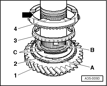
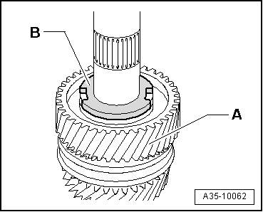
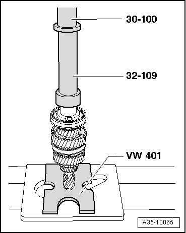
Pressing on 5th and 6th gear synchronising hub with locking collar
Note the following when performing the following steps:
l  
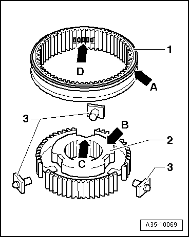
Installation position of synchronising hub: high inside collar faces 5th speed selector gear
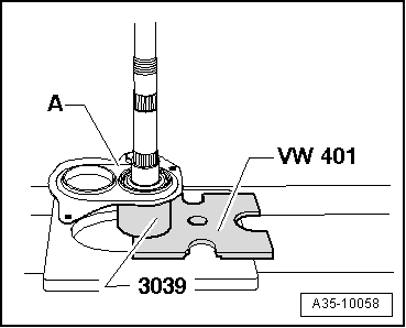
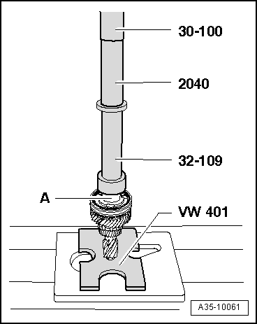
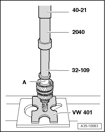
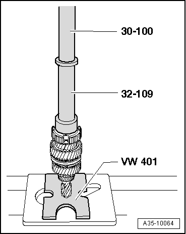
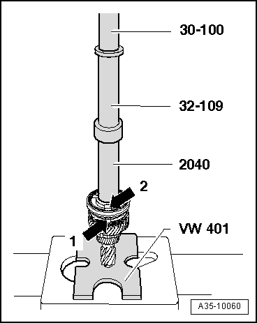
–  Fit input shaft in drilling of thrust plate -VW 401-.
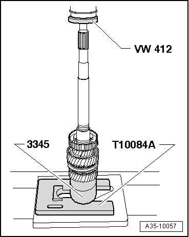
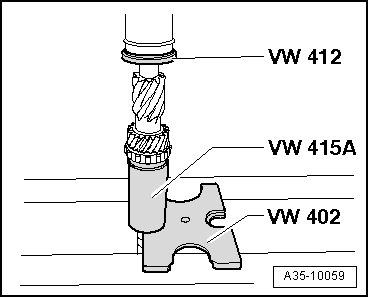
–  Position drift sleeves on centre of heated components (synchronising hub and needle bearing inner races).
–  First press on components just briefly, then stop exerting pressure and check whether drift sleeves are still positioned properly and press on as far as stop.
l  On an input shaft with “PTFE element”, the “PTFE element” must be fitted before pressing on the synchronising hub for 5th and 6th gear.
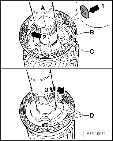
l  
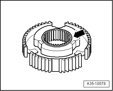
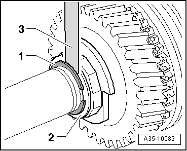
When pressing on, lugs on synchro-ring -arrow 1- must line up with recesses in synchronising hub -arrow 2-.
  A35-10060
Pressing on needle bearing inner race -A- for 6th speed selector gear
  A35-10061
–  Install 6th speed selector gear -A- with needle bearing and synchro-rings.
–  Position thrust washer -B- for 3rd speed and 6th speed selector gears on 6th speed selector gear.
  A35-10062
Pressing on needle bearing inner race -A- for 3rd speed selector gear
–  Fit 3rd speed selector gear with needle bearing and synchro-rings.
  A35-10063
Installation position of 3rd and 4th gear synchronising hub
l  The shoulder -arrow- on the synchronising hub faces towards 3rd speed selector gear.
  A35-10078
Pressing on synchronising hub for 3rd and 4th gear
l  Note installation position of synchronising hub → Fig.
l  When pressing on, lugs on synchro-rings must line up with recesses in synchronising hub.
  A35-10064
Installation position of 3rd and 4th gear locking collar
l  The groove -arrow- on the locking collar faces towards 3rd speed selector gear.
  A35-10080
Assembling 3rd and and 4th gear locking collar/synchronising hub
l  3rd and 4th gear synchronising hub is pressed on.
–  Apply a small amount of grease to convex side -arrow 1- of each of the three locking pieces -A-.
–  Fit the three locking pieces with convex side first into recesses in locking collar -B-.
l  Note installation position of locking collar → Fig..
–  Then position locking collar over synchronising hub -C- so that recesses on synchronising hub -arrow 2- align with locking pieces.
–  Then position thrust blocks -D- in synchronising hub and press thrust blocks in direction of -arrow 3- into recesses in locking collar. The locking collar must be held in the centre position.
  A35-10070
Pressing on needle bearing inner race for 4th speed selector gear
–  Fit 4th speed selector gear with needle bearing and synchro-rings.
–  Clean thread of used 12-point nut.
–  Screw 12-point nut hand-tight onto input shaft.
  A35-10065
–  Apply angled ring spanner -T10307- to 12-point nut.
–  For the next step, the end of the input shaft with the clutch plate splines must be placed in clamping device -T10306- and clamped in a vice.
  Note
t  Due to the offset centre of gravity of the input shaft, the input shaft must be supported (e.g. by a second mechanic).
t  The 12-point nut has a “left-hand thread” (turn tool anti-clockwise to fasten nut).
A - Torque wrench
–  Turn 12-point nut in direction of -arrow- and tighten to 75 Nm.
–  Then check selector gears for freedom of movement and axial play.
l  The axial play of the selector gears must be at least 0.10 mm.
  A35-10068
The thickness of the circlip -1- and the shim -2- is determined according to the following procedure:
–  The gap after fitting shim and circlip available as spare parts must be max. 0.10 mm (measured between circlip and shim).
–  Check the gap with a feeler gauge -3-.
  Note
The circlip -1- must be properly seated in the base of the groove when checking the gap.
–  Determine shim and circlip from table. Part numbers → Electronic parts catalogue “ETKA”.
The following circlips are available:
  A35-10082
Circlip thickness (mm)
1.701.801.90
1.751.85 

The following shims are available:
   
Shim thickness (mm)
0.91.11.3
1.01.2 

–  Install shim and circlip of the correct thickness as determined above.
   

Pinion shaft and hollow shaft > < Input shaft - exploded view