A4 Mk2
| Input shaft - exploded view |
| Dismantling and assembling input shaft - assembly sequence → Chapter |
 Note
Note| t | Refer to technical data when installing new gears → 6-speed manual gearbox 0A3, four-wheel drive; Rep. Gr.00. |
| t | When renewing synchro-rings, renew inner ring, intermediate ring and synchro-ring for the corresponding gear together. |
| t | Lubricate all bearings and synchro-rings on input shaft with gear oil before installing. |
| t | The 12-point nut → Item has a left-hand thread; turn nut clockwise to unfasten. |
| t | Items 8, 11 to 14, 18 to 21, 25, 28 to 31 and 34 to 37 were modified on gearboxes with spring-loaded selector forks → Fig.. Refer to → Electronic parts catalogue “(ETKA)” to allocate components. |

| 1 - | Circlip |
| 2 - | Grooved ball bearing |
| q | Renewing (gearbox removed but not dismantled) → Chapter |
| q | Renewing (gearbox dismantled) → Item |
| 3 - | Gearbox housing |
| 4 - | Needle bearing |
| q | Removing and installing → Item |
| 5 - | Circlip |
| q | Re-determining thickness → Anchor |
| 6 - | Washer |
| q | Re-determining thickness → Anchor |
| 7 - | 12-point nut, 75 Nm |
| q | With left-hand thread |
| 8 - | 4th speed selector gear |
| 9 - | Needle bearing |
| q | For 4th gear |
| 10 - | Needle bearing inner race |
| q | For 4th speed selector gear |
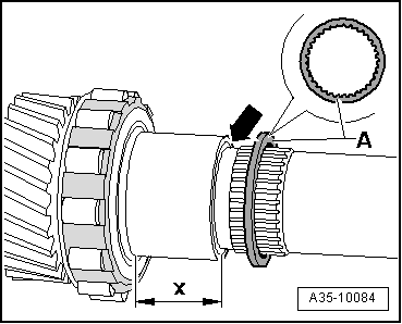
| 11 - | Inner ring for 4th gear |
| q | Installation position → Fig. |
| q | Renew if scored or if there are visible traces of wear |
| 12 - | Intermediate ring for 4th gear |
| q | Installation position → Fig. |
| q | Checking for wear → Fig. |
| 13 - | Synchro-ring for 4th gear |
| q | Installation position → Fig. |
| q | Checking for wear → Fig. |
| q | Renew if scored or if there are visible traces of wear |
| 14 - | Locking collar for 3rd and 4th gear |
| q | Assembling locking collar/synchronising hub → Fig. |
| 15 - | Locking piece |
| q | Installation position: insert locking piece into locking collar with convex side first → Fig. |
| q | Installing locking pieces (3x) → Fig. |
| 16 - | Thrust block |
| q | Installing thrust blocks (3x) → Fig. |
| 17 - | Synchronising hub for 3rd and 4th gear |
| q | Pressing off → Anchor |
| q | Pressing on → Fig. |
| q | Installation position: small shoulder on inside collar faces 3rd gear → Fig. |
| q | Assembling locking collar/synchronising hub → Fig. |
| 18 - | Synchro-ring for 3rd gear |
| q | Installation position → Fig. |
| q | Checking for wear → Fig. |
| q | Renew if scored or if there are visible traces of wear |
| 19 - | Intermediate ring for 3rd gear |
| q | Installation position → Fig. |
| q | Checking for wear → Fig. |
| 20 - | Inner ring for 3rd gear |
| q | Installation position → Fig. |
| q | Renew if scored or if there are visible traces of wear |
| 21 - | 3rd speed selector gear |
| 22 - | Needle bearing |
| q | For 3rd gear |
| 23 - | Needle bearing inner race |
| q | For 3rd speed selector gear |
| 24 - | Thrust washer |
| q | For 3rd speed and 6th speed selector gears |
| 25 - | 6th speed selector gear |
| 26 - | Needle bearing |
| q | For 6th gear |
| 27 - | Needle bearing inner race |
| q | For 6th speed selector gear |
| 28 - | Inner ring for 6th gear |
| q | Installation position → Fig. |
| q | Renew if scored or if there are visible traces of wear |
| 29 - | Intermediate ring for 6th gear |
| q | Installation position → Fig. |
| q | Checking for wear → Fig. |
| 30 - | Synchro-ring for 6th gear |
| q | Installation position → Fig. |
| q | Checking for wear → Fig. |
| q | Renew if scored or if there are visible traces of wear |
| 31 - | Locking collar for 5th and 6th gear |
| q | Assembling locking collar/synchronising hub → Fig. |
| 32 - | Synchronising hub for 5th and 6th gear |
| q | Installation position: high inside collar faces 5th speed selector gear |
| q | Pressing off → Anchor |
| q | Pressing on → Fig. |
| q | Assembling locking collar/synchronising hub → Fig. |
| 33 - | Thrust block |
| q | Installing thrust blocks (3x) → Fig. |
| 34 - | Synchro-ring for 5th gear |
| q | Installation position → Fig. |
| q | Checking for wear → Fig. |
| q | Renew if scored or if there are visible traces of wear |
| 35 - | Intermediate ring for 5th gear |
| q | Installation position → Fig. |
| q | Checking for wear → Fig. |
| 36 - | Inner ring for 5th gear |
| q | Installation position → Fig. |
| q | Renew if scored or if there are visible traces of wear |
| 37 - | 5th speed selector gear |
| 38 - | Needle bearing |
| q | For 5th gear |
| 39 - | Roller bearing |
| q | For input shaft |
| q | Do not interchange with roller bearing for hollow shaft |
| q | Pressing off → Anchor |
| q | Pressing on → Anchor |
| 40 - | Bearing mounting |
| q | The roller bearing outer race → Item cannot be renewed individually; renew bearing mounting if signs of wear are found. |
| q | The roller bearing outer race must not have any radial clearance in the bearing mounting |
| 41 - | Input shaft |
| q | Identification of input shafts → Fig. |
| q | Modification: with additional “PTFE element” for positioning needle bearing for 5th gear → Fig.; select components from → Electronic parts catalogue “ETKA” |
| 42 - | Roller bearing |
| q | Bearing for input shaft in gearbox cover |
| q | Always renew |
| q | Removing and installing → Item |
| 43 - | Gearbox cover |