
A4 Mk2
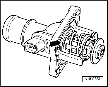
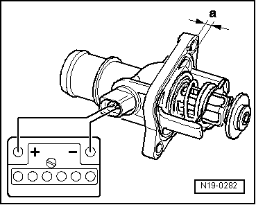
| Checking map-controlled engine cooling thermostat -F265- |

| Special tools and workshop equipment required |
| t | Hand-held multimeter -V.A.G 1526 B- |
| t | Auxiliary measuring set -V.A.G 1594 C- |
| t | CLIC hose clip pliers -V.A.G 1723- |
|
|
|
|
|
|
|
|
 Note
Note
|
|
Note
|
|
|
|
Note
|
|
Note
|
|
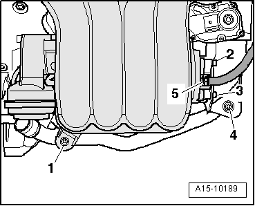
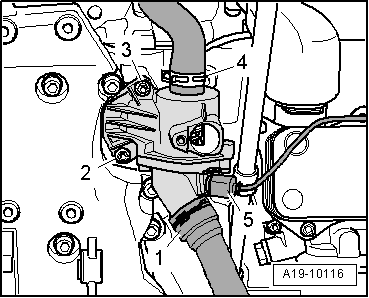
| Component | Nm |
| Intake manifold to bracket | 20 |
| Throttle valve module -J338- to intake manifold | 10 |