audi Workshop Repair Guides

Audi Workshop Service and Repair Manuals

Renewing valve stem oil seals with cylinder head installed > < Renewing camshaft oil seal
Removing and installing camshaft
Special tools and workshop equipment required
   
t  Counterhold tool -T10051-
  W00-0992
t  Puller -T10052-
t  Sealant → Electronic parts catalogue
  W00-0993
Removing
–  Vehicles with auxiliary heater: remove bolts -arrows- securing exhaust pipe for auxiliary/additional heater to noise insulation.
  A10-0407
–  Release quick-fasteners -1- and -2- and take off front noise insulation. Leave rear noise insulation in position.
–  Remove bumper cover (front) → Rep. Gr.63.
–  Move lock carrier to service position → Rep. Gr.50.
  A10-1320
–  Remove toothed belt:
t  Vehicles with hydraulically damped tensioning roller - engine codes AVB, AVF, AWX → Chapter.
t  Vehicles with friction-damped tensioning roller - engine codes AVB, AVF, AWX → Chapter.
t  Engine codes BKE, BPW, BRB, BRC → Chapter.
–  Remove camshaft sprocket securing bolts -1-.
–  Detach camshaft sprocket from hub.
  N15-0232
–  Loosen securing bolt -1- for hub; use counterhold tool -T10051-.
–  Then unscrew bolt approx. 2 turns.
  N15-0271
–  Apply puller -T10052- and align it with holes in hub.
–  Screw bolts -1- into hub.
–  Apply tension to hub by evenly tightening centre bolt -2- until hub separates from taper of camshaft.
  Note
Use 30 mm spanner to hold puller.
–  Detach hub from taper of camshaft.
  N15-0280
–  Detach crankcase breather hose at pressure control valve -arrow-.
–  Unscrew cylinder head cover bolts in the sequence -13 ... 1- and remove cylinder head cover.
  A15-0635
–  Mark rocker arm shafts with waterproof felt pen to make sure that they are reinstalled in the previous position and to avoid performing a basic setting of the unit injectors -arrows-.
–  First loosen outer bolts -1- and then inner bolts -2- on both rocker arm shafts.
–  Remove the rocker arm shafts.
–  Remove tandem pump → Rep. Gr.20.
  Note
The fuel hoses can remain connected.
  A15-0531
–  First remove the bearing caps -1-, -3- and -5-.
–  Then loosen bearing caps -2- and -4- alternately in diagonal sequence.
  Note
t  Make sure that the camshaft bearing shells are not interchanged.
t  Mark allocation of camshaft bearing shells on rear with a waterproof felt-tip pen.
–  Remove camshaft.
  A15-0532
Installing
  Note
Renew the bolts tightened with specified tightening angle.
l  The crankshaft sprocket must be locked in position:
A - For engine codes AVB, AVF, AWX: with crankshaft stop -T10050-
B - For engine codes BKE, BPW, BRB, BRC: with crankshaft stop -T10100-
  Note
t  The markings on the toothed belt sprocket and the crankshaft stop -arrow- must align. The pin of the crankshaft stop must engage in the aperture in the sealing flange.
t  Make sure that the used camshaft bearing shells are not interchanged (note marking).
t  When installing the camshaft, make sure that the retaining lugs on the bearing shells are correctly seated in the bearing caps and the cylinder head.
  N15-10159
–  Lubricate contact surfaces of camshaft.
–  Install camshaft in TDC position:
l  The cams for cylinder 1 must point upwards evenly on camshaft -arrows-.
  Note
  A15-0530
If the bearing caps are fitted with the cylinder head removed, the washers for the cylinder head bolts → Item must first be fitted.
–  Tighten bearing caps -2- and -4- alternately in diagonal sequence.
  A15-0532
–  Apply a thin and even coat of sealant to surfaces -1- of bearing caps 1 and 5; for sealant refer to → Electronic parts catalogue.
  Note
Make sure no sealant gets into the grooves -arrows- or onto the other surfaces.
  N15-0270
–  Install bearing caps -1-, -3- and -5- and tighten.
l  Bearing cap -5- must be flush with the outer edge of the cylinder head, otherwise the tandem pump may leak.
–  Install camshaft oil seal → Chapter.
  A15-0532
–  Before inserting rocker arm shaft, check whether all ball studs -2- and O-rings -1- have been installed in unit injectors.
  A15-10179
–  Install rocker arm shafts. When doing so, note the markings made on removal -arrows-.
–  Tighten bolts on each section (I and II) as follows: first tighten inner bolts -2- and then outer bolts -1-.
  A15-0531
–  Attach hub to camshaft.
–  Tighten securing bolt -1- (use counterhold -T10051-).
  N15-0271
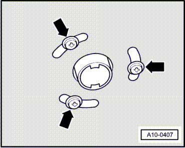
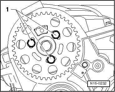
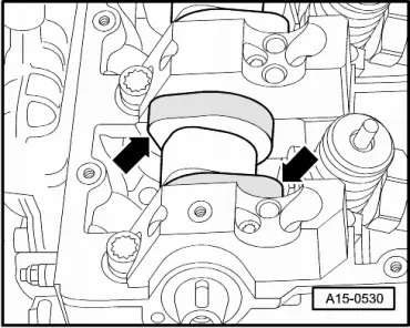
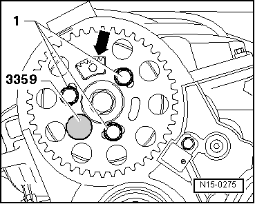
–  Push camshaft sprocket onto hub.
l  Toothed segment -arrow- of camshaft sprocket must be at top.
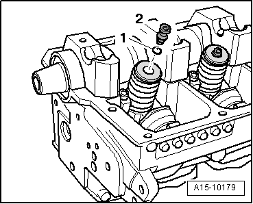
–  Screw in bolts -1- finger-tight.
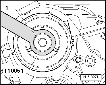
–  Lock hub with locking pin -3359-.
The remaining installation steps are carried out in the reverse sequence.
–  Fit toothed belt (adjust valve timing):
t  Vehicles with hydraulically damped tensioning roller - engine codes AVB, AVF, AWX → Anchor.
t  Vehicles with friction-damped tensioning roller - engine codes AVB, AVF, AWX → Anchor.
t  Engine codes BKE, BPW, BRB, BRC → Anchor.
–  Install tandem pump → Rep. Gr.20.
–  If the rocker arm shafts or ball studs and adjuster screws were renewed, the unit injectors must be adjusted → Rep. Gr.23.
–  Install cylinder head cover → Anchor.
–  Install lock carrier with attachments → Rep. Gr.50.
–  Install bumper cover (front) → Rep. Gr.63.
  Note
t  After installing the camshaft, the engine must NOT be started for about 30 minutes. The hydraulic tappets have to settle (otherwise valves will strike pistons).
t  After working on the valve gear, turn the engine carefully at least 2 rotations to ensure that none of the valves make contact when the starter is operated.
Tightening torques
  N15-0275
ComponentNm
Bearing cap to cylinder head8 + 90° 1)2)
Rocker arm shaft to cylinder head20 + 90° 1)2)
Hub to camshaft100
l  1) Renew bolts.
l  2) 90° = one quarter turn.


Renewing valve stem oil seals with cylinder head installed > < Renewing camshaft oil seal