
A4 Mk2
| Removing and installing cylinder head |
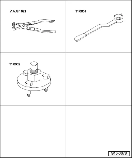
| Special tools and workshop equipment required |
| t | Hose clip pliers -V.A.G 1921- |
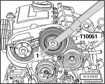
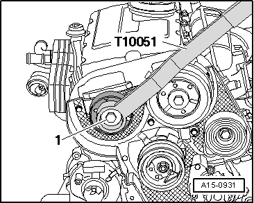
| t | Counterhold tool -T10051- |
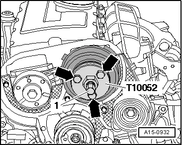
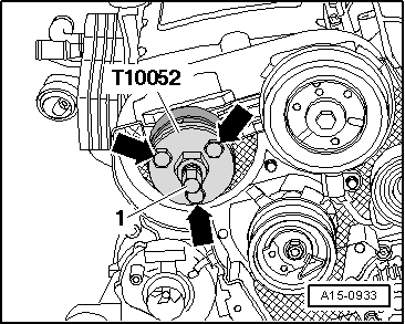
| t | Puller -T10052- |
| t | Safety goggles |
| t | Protective gloves |
|
 Caution
|
|
 Note
Note
|
|
|
|
Note
|
|
Note
|
|
|
|
|
|
 WARNING
|
|
|
|
|
|
|
|
|
|
|
|
|
|
|
|
|
|
|
|
|
|
Note
|
|
Note
|
|
|
|
|
|
|
|
|
|
|
|
|
|
|
|
|
|
Note
|
|
Note
|
|
|
|
|
|
Note
|
|
|
|
|
|
Note
|
|
|
|
|
|
|
Note
|
|
|
|
|
|
|
|
|
|
|
|
|
|
|
|
| Component | Nm | |||||||
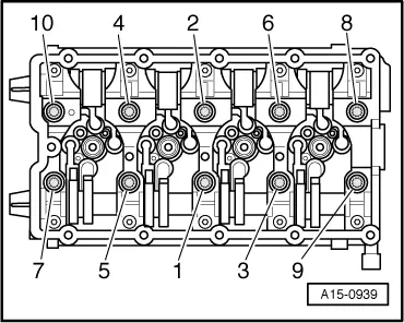
| Rocker arm shaft to cylinder head | 20 + 90° 1)2) | |||||||
| Rear toothed belt cover to cylinder head | 10 3) | |||||||
| Hall sender to cylinder head | 10 3) | |||||||
| Stud to cylinder head | 15 | |||||||
| Hub to camshaft | 100 | |||||||
| Oil supply pipe to turbocharger | 22 | |||||||
| Bracket for oil supply pipe to exhaust manifold | 22 | |||||||
| Oil supply pipe to oil filter bracket | 22 | |||||||
| Oil pressure switch to oil filter bracket | 20 | |||||||
| Oil return pipe to cylinder block | 30 | |||||||
| Guide tube for | Engine lifting eye | 10 | ||||||
| oil dipstick to: | Oil filter bracket | 10 | ||||||
| Bracket for | Turbocharger | 20 | ||||||
| Turbocharger to: | Cylinder block | 40 | ||||||
| Stop for torque reaction support to lock carrier | 28 | |||||||
| Hose clips (9 mm wide) | 3 | |||||||
| Hose clips (13 mm wide) | 5.5 | |||||||
| ||||||||