audi Workshop Repair Guides

Audi Workshop Service and Repair Manuals

Checking hydraulic tappets > < Renewing valve stem oil seals with cylinder head installed
Renewing valve stem oil seals with cylinder head removed
   
Renewing valve stem oil seals with cylinder head removed
Special tools and workshop equipment required
t  Valve stem seal puller -3364-
t  Valve stem seal fitting tool -3365-
t  Removal and installation device for valve cotters -VAS 5161-
t  Guide plate for 2.0 ltr. TDI engine -VAS 5161/21-
t  Socket -T50001-

   
t  
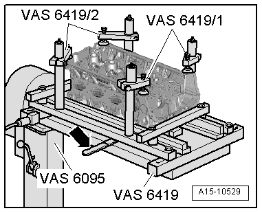
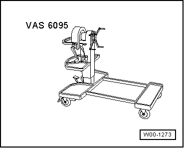
Engine and gearbox support -VAS 6095-
t  
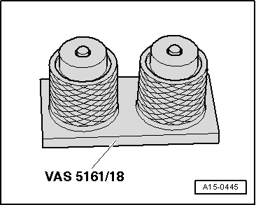
Cylinder head tensioning device -VAS 6419-
Handling ceramic glow plugs:
The Audi A4 with 4-cylinder 2.0 ltr. 4-valve TDI engine with particulate filter is equipped exclusively with NGK ceramic glow plugs.
  Note
NGK ceramic glow plugs are colour-coded with a white, or possibly “silver-coloured” seal.
  Caution
Important: Always observe the special instructions for handling ceramic glow plugs.
  Caution
t  Due to the special properties of the material used, ceramic glow plugs are easily damaged and require extra care when handling and removing/installing. Always observe the special instructions when removing and installing ceramic glow plugs → Rep. Gr.28.
t  Use only the approved type of ceramic glow plugs → Electronic parts catalogue.
t  Transport and store only in original packaging or packed separately in bubble wrap.
t  Do not remove new ceramic glow plugs from packaging until they are ready to be fitted.
t  Ceramic glow plugs are sensitive to knocks and bending. For this reason, ceramic glow plugs which have been dropped (even from a height of only about 2 cm) must not be installed, even if no damage is apparent (hair-line cracks may not be visible).
t  Always install a new ceramic glow plug if you are not sure the old one is in perfect condition.
t  Damaged glow plugs (e.g. heater pin of the glow plug is damaged) will invariably cause engine damage.
t  If the heater pin of the glow plug is damaged, the fragments must be removed from the combustion chamber before starting the engine for the first time, otherwise this will invariably cause mechanical damage (piston seizure).
Procedure
–  Remove camshafts → Chapter.
–  Remove unit injectors → Rep. Gr.23.
  W00-1273
–  Remove glow plugs using socket -T50001-.
  A23-0218
–  Attach tensioning device -VAS 6419- to engine and gearbox support -VAS 6095-.
–  Secure cylinder head in tensioning device -VAS 6419- as illustrated.
–  Connect compressed air line to tensioning device -VAS 6419-.
–  Using lever -arrow-, slide air pad under combustion chamber where valve stem oil seal is to be removed.
–  Apply just enough compressed air to bring air pad into contact with valve heads.
  A15-10529
–  Fit guide plate -VAS 5161/21-1- onto cylinder head.
–  Secure guide plate using the knurled screws -VAS 5161/21-3-.
–  Insert drift -VAS 5161/3- into guide plate and knock valve cotters loose using a plastic hammer.
  A15-10094
–  Secure snap-in device -VAS 5161/6- with engaging fork -VAS 5161/5- to cylinder head.
–  Slide knurled spacer ring -VAS 5161/21-5- onto assembly cartridge -VAS 5161/8-.
–  Insert assembly cartridge into guide plate.
–  Attach pressure fork -VAS 5161/2- to snap-in device and push assembly cartridge down.
–  At the same time, turn knurled screw of assembly cartridge clockwise until tips engage in valve cotters.
–  Move knurled screw back and forth slightly; the valve cotters are thus forced apart and taken up by the assembly cartridge.
–  Release pressure fork.
–  Take off assembly cartridge with knurled spacer ring.
–  Remove valve spring plate and valve spring.
  A15-10506
–  Remove valve stem oil seals using the valve stem seal puller -3364-.
  Note
  A15-10007
A plastic sleeve -A- is included with the new valve stem oil seals.
–  Fit plastic sleeve -A- onto the valve stem to prevent damage to the new valve stem oil seal -B-.
–  Lightly lubricate sealing lip of valve stem oil seal.
–  Slip valve stem oil seal over plastic sleeve.
–  Carefully press valve stem oil seal onto valve guide using valve stem seal fitting tool -3365-.
–  Remove plastic sleeve.
  A15-0282
–  If valve cotters have been removed from assembly cartridge -VAS 5161/8-, they need to be put into insertion device -VAS 5161/18- first.
  Note
Larger diameter of valve cotters faces upwards.
–  Press assembly cartridge onto insertion device from above and take up valve cotters.
–  Insert valve spring and valve spring plate.
  A15-0445
–  Insert assembly cartridge into guide plate.
–  Press down pressure fork and pull up knurled screw, thus inserting the valve cotters.
–  Release pressure fork with knurled screw still in pulled position.
–  Repeat procedure for each valve.
Assembling
Installation is carried out in the reverse order; note the following:
–  Install unit injectors → Rep. Gr.23.
–  Install camshafts → Chapter.
–  Install glow plugs → Rep. Gr.28.
  A15-10506

Checking hydraulic tappets > < Renewing valve stem oil seals with cylinder head installed