
A4 Mk2
|
|
|
|
|
|
|
 Note
Note
|
|
|
|
Note
Note
|
|
|
|
Note
|
|
|
|
Note
|
|
|
|
|
|
|
|
|
|
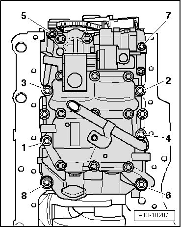
| Component | Nm | ||||||||
| Balance shaft assembly | M7 | 13 + 90° 1)2) | |||||||
| to cylinder block | M8 | 20 + 90° 1)2) | |||||||
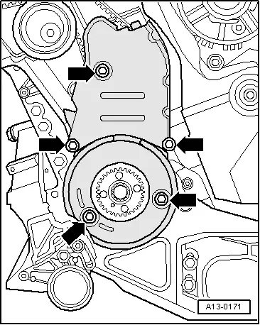
| Chain tensioner to balance shaft assembly | 9 | ||||||||
| Chain sprocket to balance shaft | 10 + 90° 1)2) | ||||||||
| Cover for | Chain tensioner | 5 3) | |||||||
| chain sprocket to: | Oil pump | 5 3) | |||||||
| Toothed belt cover to engine | 10 3) | ||||||||
| |||||||||