audi Workshop Repair Guides

Audi Workshop Service and Repair Manuals

Removing and installing balance shaft assembly with chain drive > < Sump, oil pump, balance shaft assembly with chain drive - exploded view
Removing and installing sump
   
Removing and installing sump
Special tools and workshop equipment required
t  Support bracket -10-222 A-
t  Locating pins -3393-
t  Used oil collection and extraction unit -V.A.G 1782-
t  Workshop hoist -VAS 6100-
t  Allen key (long reach) -T10058-
t  Mud wing compensation plate -T40045-
t  Electric drill with plastic brush attachment
t  Safety goggles
t  Sealant → Electronic parts catalogue

Removing
  Note
All cable ties which are released or cut open when removing must be fitted in the same position when installing.
–  Remove both front wheels.
–  Remove poly V-belt → Chapter.
   
–  Remove the rubber sealing strip from the edges of the wing mounting flanges.
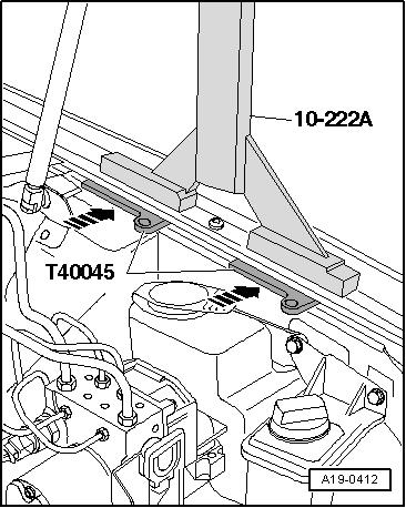
–  Place compensation plates -T40045- between the wing mounting flange and the body flange underneath, so that the support bracket -10-222 A- does not damage the edges of the wings.
  A19-0412
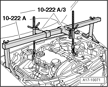
–  Set up support bracket -10-222 A- with adapters -10-222/3- on wing panel flanges.
–  Attach spindles to the engine lifting eyes as illustrated.
–  Use spindles to slightly take up weight of engine.
  A17-10071
–  Place used oil collection and extraction unit -V.A.G 1782- under engine and drain engine oil.
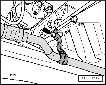
–  Unbolt refrigerant pipe bracket from sump -arrow-.
  A10-10286
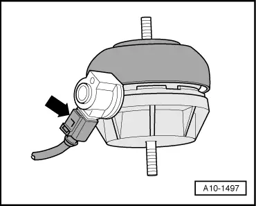
–  Unplug electrical connector -arrow- at engine mounting (left-side).
  A10-1497
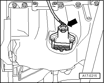
–  Unplug electrical connector -arrow- at oil level and oil temperature sender -G266-.
  A17-0215
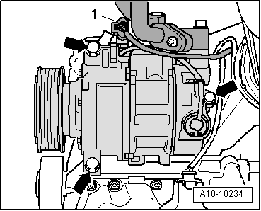
–  Unplug electrical connector -1- for magnetic clutch of air conditioner compressor.
–  Move wiring harness clear.
  Caution
The air conditioner refrigerant circuit must not be opened.
–  Unscrew air conditioner compressor from bracket -arrows-.
–  Tie up refrigerant line to side.
  Note
To prevent damage to the refrigerant lines, ensure that the pipes and hoses are not stretched, kinked or bent.
–  Tie up air conditioner compressor and condenser with hoses/pipes connected to side of vehicle.
  A10-10234
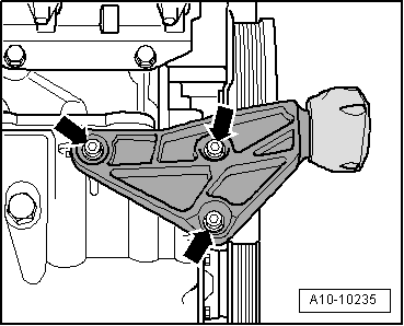
–  Unscrew bolts -arrows- and remove torque reaction support from sump.
  A10-10235
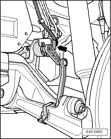
–  Unplug electrical connector -arrow- at front left vehicle level sender -G78-.
  A40-0460
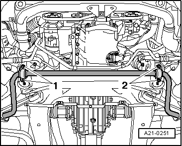
–  Unbolt anti-roll bar mountings -1- and -2-.
  A21-0251
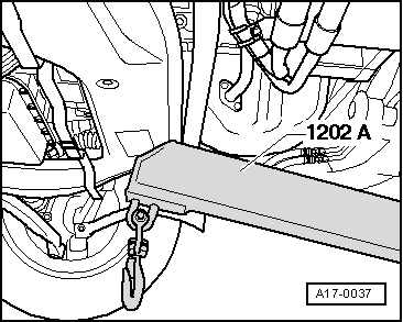
–  Support subframe using workshop hoist.
  A17-0037
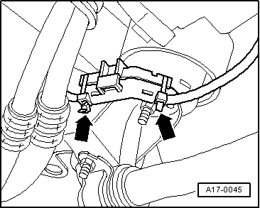
–  Cut open the cable ties -arrows-, open bracket for starter wire and take out the electrical wire.
  A17-0045
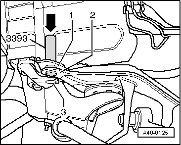
–  Before detaching subframe, use locating pins -3393- to check whether holes -1- and -2- on subframe are in alignment.
  Caution
If this is not the case, wheel alignment must be performed after installing subframe.
  A40-0125
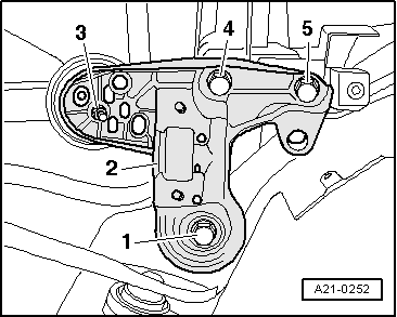
–  Unscrew nut -3- at bottom of engine mounting.
–  Unscrew bolts -4- and -5- on console for engine mounting.
–  Unscrew bolt -1- (front) for subframe and remove console for engine mounting -2-.
–  Repeat procedure on other side of vehicle.
  A21-0252
–  Lower subframe slowly using workshop hoist.
  A17-0037
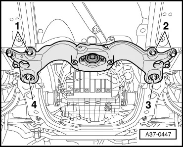
–  Remove bolts -3- and -4-.
–  Unscrew bolts -1- and -2- three turns each.
  A37-0447
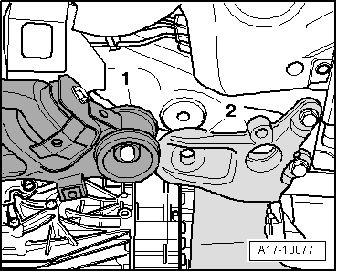
–  Pull subframe -1- towards the front and allow subframe to make contact with tunnel cross member -2- (as shown in illustration) -arrow-.
  A17-10077
–  Lift engine up slightly using spindles of support bracket -10-222 A-; make sure the selector linkage and exhaust system have adequate clearance.
  A17-10071
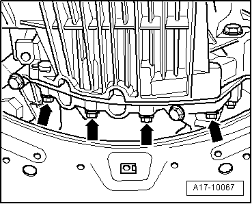
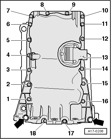
–  Unscrew gearbox/sump bolts -arrows-.
  A17-10067
–  Unscrew M10 bolts -arrows-.
–  Slacken bolts -1 ... 18- in diagonal sequence.
  Note
t  Bolts -17- and -18- can only be unscrewed using Allen key (long reach) -T10058-.
t  When unscrewing bolts -17- and -18- they come into contact with flywheel. However, this does not damage bolts and tapped holes.
–  Take off sump; if necessary loosen it by striking lightly with a rubber hammer.
Installing
Installation is carried out in the reverse order; note the following:
  Note
t  Renew seal.
t  Renew the bolts tightened with specified tightening angle.
t  Hose connections and hoses for charge air system must be free of oil and grease before assembly.
t  Secure all hose connections with the correct type of hose clips (same as original equipment) → Electronic parts catalogue.
t  To ensure that the charge air hoses can be properly secured at their connections, spray rust remover onto the worm thread of used hose clips before installing.
t  Fit all cable ties in the original positions when installing.
  A17-0208
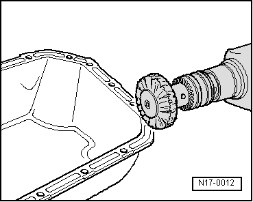
–  Remove sealant residue from sump and cylinder block with rotating plastic brush or similar.
  WARNING
Wear safety goggles.
–  Clean sealing surfaces; they must be free of oil and grease.
  N17-0012
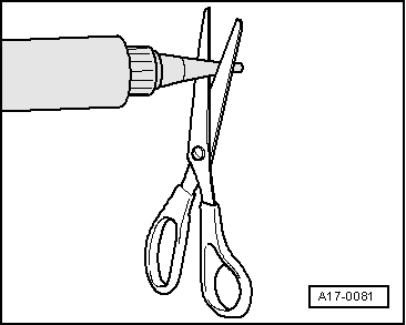
–  Cut off tube nozzle at front marking (nozzle approx. 2 mm Ø).
  A17-0081
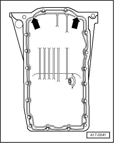
–  Apply bead of sealant onto the clean sealing surface of the sump as shown in the illustration.
l  Thickness of sealant bead: 2 ... 3 mm
  Note
t  Sealant bead must not be wider than 3 mm, otherwise excess sealant could ingress into sump and clog strainer in oil intake pipe.
t  Take particular care when applying sealant bead in area of rear sealing flange -arrows-.
t  The sump must be installed within 5 minutes after applying sealant.
  A17-0041
–  Immediately install sump and tighten bolts in the sequence indicated:
1.  Pre-tighten bolts -1 ... 18- in diagonal sequence to 5 Nm.
2.  Tighten bolts securing sump to gearbox to 45 Nm.
3.  Tighten bolts M10 -arrows- to 40 Nm.
4.  Tighten bolts -1 ... 18- in diagonal sequence to 15 Nm.
  Note
t  Bolts -17- and -18- can only be screwed in using Allen key (long reach) -T10058-.
t  When screwing in bolts -17- and -18- they come into contact with flywheel. However, this does not damage bolts and tapped holes.
  Note
  A17-0208
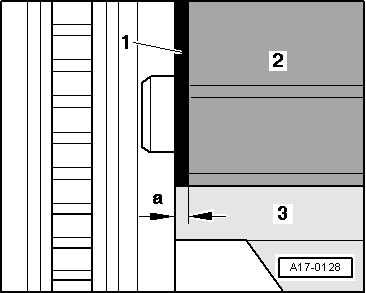
t  When installing the sump -3- with the engine removed from the vehicle, make sure that it is positioned flush with the intermediate plate -1- at the flywheel end. In other words, the sump should protrude by 0.8 mm (distance -a-) from cylinder block -2-.
t  After fitting sump assembly, the sealant must dry for approx. 30 minutes. Then (and only then) fill the engine with engine oil.
  A17-0128
If it was not possible to insert both locating pins -3393- fully into holes in subframe before detaching subframe, it will be necessary to perform a wheel alignment check.
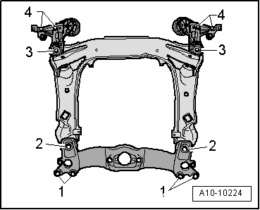
–  Tighten new bolts for subframe, consoles for engine mountings and tunnel cross member only to the specified torque (do not turn further); tighten bolts to final setting only after performing wheel alignment check.
1 - 65 Nm
2 - 110 Nm
3 - 110 Nm
4 - 75 Nm
  WARNING
The vehicle must not be driven at this stage.
–  Perform wheel alignment check after completing all installation work → Rep. Gr.44.
  A10-10224
A wheel alignment check is not necessary if you were able to insert both locating pins -3393- fully into holes -1- and -2- in subframe before detaching subframe.
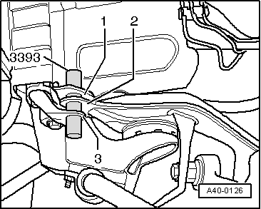
–  Locate subframe in relation to body with locating pins -3393- before tightening bolts.
l  Holes -1- and -2- on subframe and hole -3- in console for engine mounting must be in alignment on both sides of vehicle.
–  Secure subframe → Rep. Gr.40.
All vehicles:
Remaining installation steps are carried out in reverse sequence; note the following:
–  Install anti-roll bar → Rep. Gr.40.
–  Install air conditioner compressor → Rep. Gr.87.
–  Install poly V-belt → Chapter.
  A40-0126
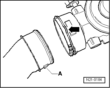
–  When installing air intake hoses with plug-in connectors, ensure that the securing clip -arrow- engages audibly on the retaining lug -A-.
–  Fill up with engine oil and check oil level → Booklet803 or → Booklet805.
Tightening torques
  N21-0184
ComponentNm
Oil drain plug30
Sump to:M715
Cylinder blockM1040
Sump to gearbox45
Torque reaction support to sump23
Engine mounting to console for engine mounting40
Console for engine mounting to longitudinal member75


Removing and installing balance shaft assembly with chain drive > < Sump, oil pump, balance shaft assembly with chain drive - exploded view