
A4 Mk2
| Cylinder head - exploded view of components |
 Note
Note| t | Never set down cylinder head on workbench, as this could damage injectors and glow plugs. |
| t | A pressure limiting valve (for lubrication points in cylinder head) is screwed into each cylinder head. Tightening torque: 25 Nm. |

| 1 - | Cylinder head |
| q | Removing: left-side → Chapter; right-side → Chapter |
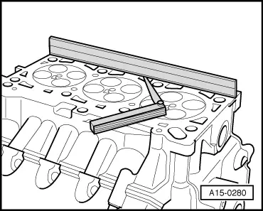
| q | Checking for distortion → Fig. |
| q | Cylinder heads must not be machined on diesel engines |
| q | Installing → Chapter |
| q | If renewed, refill system with fresh coolant |
| 2 - | Gasket for cylinder head cover |
| q | Renew if damaged or leaking |
| q | Before fitting gasket apply sealant at sealing points → Chapter „Removing and installing cylinder head cover (left-side)“, → Chapter „Removing and installing cylinder head cover (right-side)“ |
| 3 - | Cylinder head bolt |
| q | Renew |
| q | Note sequence when loosening: cylinder head (left-side) → Anchor, cylinder head (right-side) → Anchor |
| q | Note correct sequence when tightening → Anchor |
| 4 - | Cylinder head cover |
| q | Removing and installing: left-side → Chapter, right-side → Chapter |
| q | Renew cylinder head cover if injector seals are damaged |
| 5 - | Deflector ring |
| q | Renew if damaged |
| 6 - | Seal |
| q | Renew if damaged or leaking |
| 7 - | Filler cap |
| 8 - | Injector pipes |
| q | Use ring spanner -3035- for removal |
| q | Always remove pipework complete |
| q | Do not alter shape |
| q | Tighten to 30 Nm |
| 9 - | Return pipe |
| 10 - | Seal |
| q | Renew |
| 11 - | Banjo bolt, 5 Nm |
| 12 - | Intake manifold |
| q | Removing and installing → Rep. Gr.23 |
| 13 - | 10 Nm |
| q | Tighten in stages and in diagonal sequence |
| 14 - | Gasket |
| q | Renew |
| 15 - | Dowel sleeve |
| q | 2x |
| q | Take care to prevent dowel sleeves dropping into intake ports |
| 16 - | 10 Nm |
| q | Tighten in stages and in diagonal sequence |
| 17 - | Heat shield for exhauster pump |
| q | Depending on version |
| 18 - | 10 Nm |
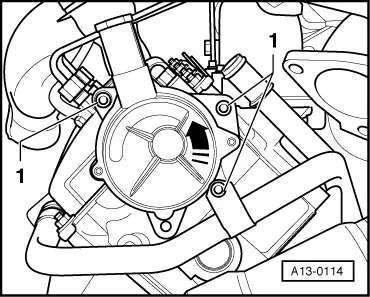
| 19 - | Exhauster pump |
| q | For brake servo |
| q | Removing and installing → Fig. |
| 20 - | O-rings |
| q | For exhauster pump |
| q | Renew |
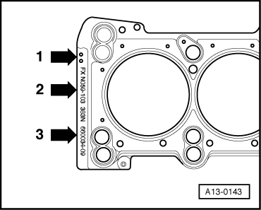
| 21 - | Cylinder head gasket |
| q | Different thicknesses |
| q | Note marking → Fig. |
| q | Renewing → Chapter |
| q | Installation position: Part No. towards cylinder head |
| q | If renewed, refill system with fresh coolant |
|
|
Note
|
|
|
|