audi Workshop Repair Guides

Audi Workshop Service and Repair Manuals

Removing and installing cylinder head cover (right-side) > < Cylinder head - exploded view of components
Removing and installing cylinder head cover (left-side)
Special tools and workshop equipment required
   
t  Ring spanner -3035-
  W00-0269
t  Torque wrench -V.A.G 1331- with 17 mm attachment (commercially available)
t  Sealant → Parts catalogue
  W00-0427
Removing
  Note
All cable ties which are released or cut open when removing must be fitted in the same position when installing.
–  Remove intake manifold (front section) → Rep. Gr.23.
–  Unbolt coolant expansion tank -arrow-.
–  Unplug electrical connector for coolant shortage indicator switch -F66- at expansion tank (bottom) and move expansion tank to one side (coolant hoses -1 ... 3- remain attached).
–  Unfasten cable clamp at cylinder head cover and move wiring harness clear to one side.
–  Mark position of retaining clips on injector pipes (e.g. with felt-tip pen).
–  Mark injector pipes according to cylinder (e.g. with felt-tip pen).
–  Disconnect injector pipes one by one with ring spanner -3035-.
  A10-0989
–  Disconnect return pipe from injectors -1-.
–  Unscrew nuts -arrows- for cylinder head cover and detach cylinder head cover.
Installing
Installation is carried out in the reverse order; note the following:
  Note
t  Renew seals for return pipes.
t  Renew cylinder head cover gaskets if damaged.
t  Renew cylinder head cover if injector seals are damaged.
t  Fit all cable ties in the original positions when installing.
  A15-0269
–  Clean sealing surfaces; they must be free of oil and grease.
–  Fit semi-circular seal -1-.
l  Installation position: Parts number should be visible from outside; straight side of sealing surface should be flush with sealing surface of cylinder head.
–  Draw a bead of sealant (Ø approx. 3 mm) over the semi-circular seal so that about 5 mm projects out at both ends -right arrow-.
  A15-0502
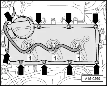
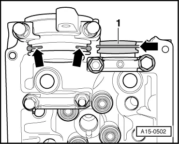
–  Apply a drop of sealant (Ø approx. 5 mm) to all sealing points at joints between cylinder head and camshaft bearing caps.
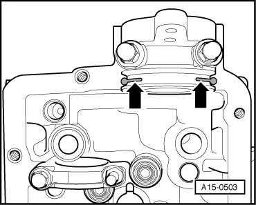
–  Draw a bead of sealant (Ø approx. 3 mm) up to about half the height of camshaft bearing caps.
–  Tighten nuts for cylinder head cover diagonally and in stages.
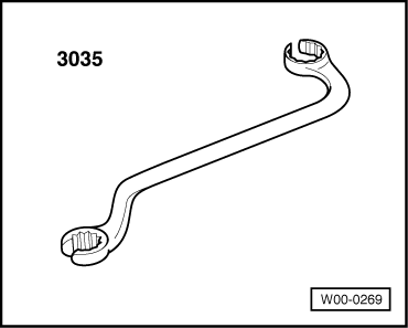
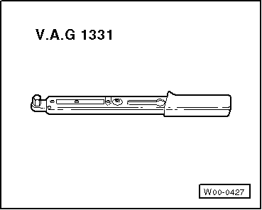
–  Fit injector pipes one at a time, working from bottom to top and secure using torque wrench -V.A.G 1331- and 17 mm attachment (commercially available).
  Note
t  Ensure stress-free installation of injector pipes.
t  Make sure that retaining clips are positioned correctly.
–  Install intake manifold (front section) → Rep. Gr.23.
Tightening torques
  A15-0503
ComponentNm
Cylinder head cover to cylinder head10 → Note
Return pipes to injectors5
Injector pipes to:Injectors30
 Injection pump30

1)  Re-tighten to 10 Nm when engine is warm.
   

Removing and installing cylinder head cover (right-side) > < Cylinder head - exploded view of components