
A4 Mk2
| Removing and installing camshafts |

| Special tools and workshop equipment required |
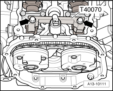
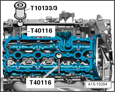
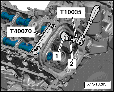
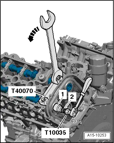
| t | Special wrench -T10035- |
| t | Puller -T10133/3- |
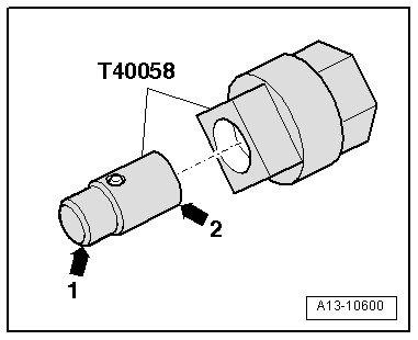
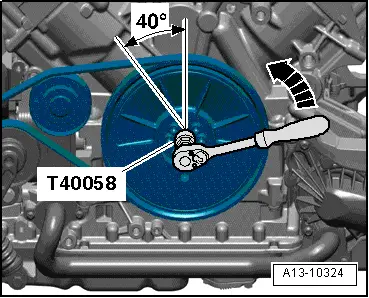
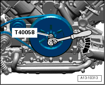
| t | Adapter -T40058- |
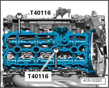
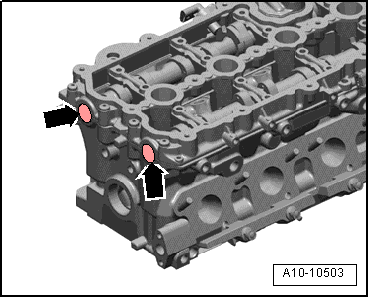
| t | Locating pins for retaining frame -T40116- |
| t | Electric drill with plastic brush attachment |
| t | Safety goggles |
| t | Sealant → Electronic parts catalogue |
 Note
Note
|
|
|
|
|
|
 Caution
|
|
|
|
Note
|
|
Note
|
|
 WARNING
|
|
|
|
Note |
|
|
|
Note
|
|
Note
|
|
|
|
|
|
|
|
Note
|
|
|
|
|
|
|
|
Note
|
|
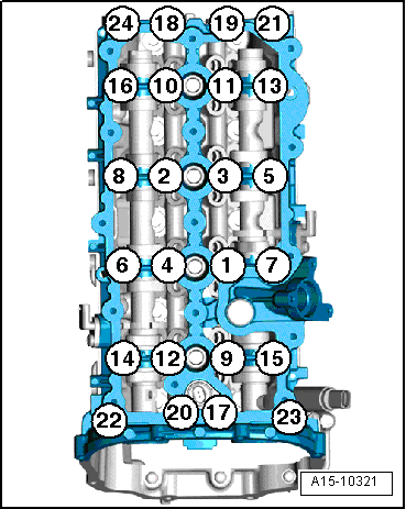
| Component | Nm |
| Retaining frame to cylinder head | 8 |