
A4 Mk2
|
|
|
 Note
Note
|
|
Note
|
|
|
|
|
|
|
|
Note
|
|
Note
Note
|
|
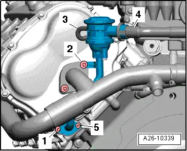
| Component | Nm | |
| Connecting pipe to: | Cylinder head | 9 |
| Combination valve for secondary air system | 9 | |