audi Workshop Repair Guides

Audi Workshop Service and Repair Manuals

Checking compression > < Intake manifold (vehicles without fuel return line) - exploded view of components
Removing and installing intake manifold
Removing
  Note
All cable ties which are released or cut open when removing must be fitted in the same position when installing.
–  Move lock carrier to service position → Chapter.
   
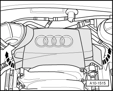
–  Pull off rear engine cover panel -arrows-.
  A10-1515
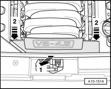
–  Detach the front engine cover panel -arrows 1 and 2-.
  A10-1514
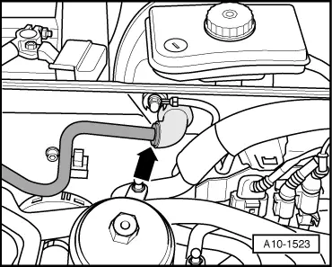
–  Detach vacuum line -arrow- going to brake servo at bulkhead.
  A10-1523
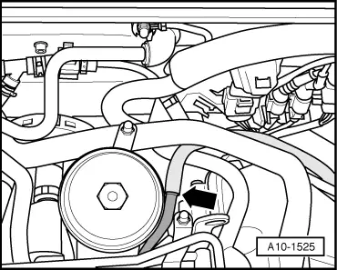
–  If fitted, detach vacuum line -arrow- going to vacuum reservoir.
  A10-1525
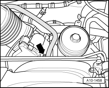
–  Detach vacuum hose -arrow- at intake manifold.
  A10-1458
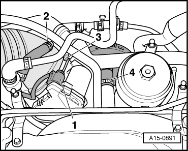
–  Unplug electrical connector -1- at throttle valve module -J338-.
–  Detach vacuum hose -2-.
–  Remove air intake hose -3-.
–  Disconnect hose -4- for crankcase breather system at intake manifold.
  A15-0891
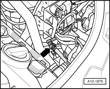
–  If fitted, separate vacuum line at the point marked with an -arrow-.
  A10-1875
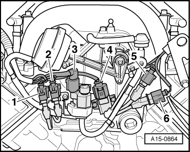
–  Pull electrical connectors -1 to 4- forwards out of brackets on intake manifold.
  Note
Do not unplug electrical connectors.
  A15-0864
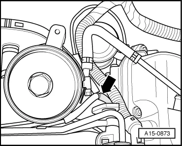
–  Detach vacuum hose -arrow- from T-piece.
  A15-0873
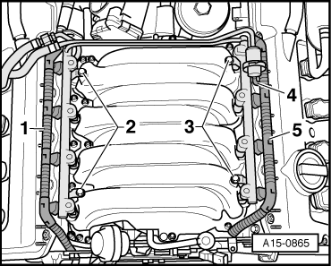
–  Unplug connector rails -1- and -5- at injectors.
–  On vehicles with fuel return line, disconnect vacuum line -4- at fuel pressure regulator.
–  Unscrew securing bolts -2- and -3- for fuel rail.
–  Pull fuel rail pipe together with injectors off intake manifold (pull off evenly from the top) and place it on a clean cloth in the engine compartment.
  Note
Make sure the removed injectors do not become soiled.
  A15-0865
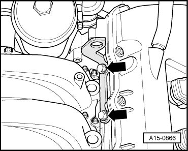
–  Unscrew engine lifting eye (rear left) -arrows-.
  A15-0866
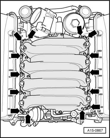
–  Unscrew and remove intake manifold -arrows-.
  Note
Seal intake ports on cylinder heads with clean cloths.
Installing
Installation is carried out in the reverse order; note the following:
  Note
t  Renew gaskets, seals and O-rings.
t  Secure all hose connections with the correct type of hose clips (same as original equipment) → Parts catalogue.
t  Fit all cable ties in the original positions when installing.
  A15-0867
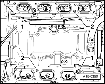
–  Remove securing bolts -1- to renew gaskets for intake manifold.
–  Observe locating pins -2- when fitting intake manifold.
  A15-0350
–  Tighten bolts on intake manifold in stages and in diagonal sequence -arrows-.
–  Install lock carrier with attachments → Rep. Gr.50.
  A15-0867
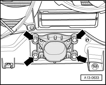
–  Allow stop for torque reaction support to rest on rubber buffer for torque reaction support under its own weight and tighten bolts -arrows-.
–  Install bumper cover (front) → Rep. Gr.63.
–  Check headlight adjustment → Booklet803 or → Booklet805.
Tightening torques
  A13-0633
ComponentNm
Securing bolt to cylinder head0.6
Intake manifold to cylinder head10
Engine lifting eye to cylinder head22
Fuel rail to intake manifold10
Stop for torque reaction support to lock carrier28


Checking compression > < Intake manifold (vehicles without fuel return line) - exploded view of components