audi Workshop Repair Guides

Audi Workshop Service and Repair Manuals

Removing and installing lambda probe downstream of catalytic converter, bank 2 (left) > < Removing and installing lambda probe upstream of catalytic converter, bank 2 (left)
Motronic injection and ignition system (8-cyl.)
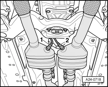
Removing and installing lambda probe upstream of catalytic converter, bank 1 (right)
Removing and installing lambda probe downstream of catalytic converter, bank 1 (right)
 
W00-0206

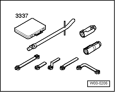
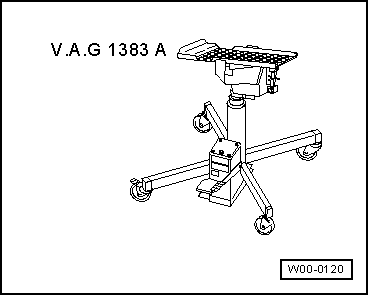
Special tools and workshop equipment required

  • ◆ Ring spanner set 3337

 
W00-0120
  • ◆ Engine/gearbox lifter V.A.G 1383 A
 
A10-1515

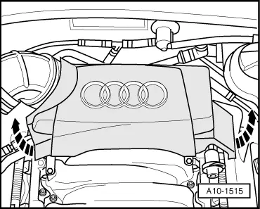
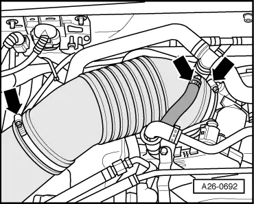
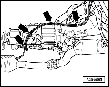
Removing

Note:

All cable ties unfastened or cut open on removal are to be re-attached in same position on installation.

  • ‒ → Detach rear engine cover -arrows-.

 
A10-1030
  • ‒ → Detach cover -1- on right of engine compartment.
 
A26-0692
  • ‒ → Remove air hose -arrows-.

 
A24-0717
  • ‒ → Take connectors -1 ... 4- out of holder on right of bulkhead.
  • ‒ Unplug connector -4-.
  • ‒ Lay bare lambda probe wiring downwards.
 
A10-0407
  • ‒ Unscrew front right wheel.
  • ‒ → On vehicles with auxiliary heater, screw out bolts -arrows- for exhaust pipe of auxiliary/additional heater at noise insulation.

 
A10-1519
  • ‒ → Unfasten quick-release fasteners -1-, screw out bolts -2- and detach noise insulation.
 
A10-0968
  • ‒ → Unscrew holder for noise insulation -arrows-.

 
A34-0493
  • ‒ → Detach universal mount V.A.G 1359/2 from engine/gearbox lifter V.A.G 1383 A and place wooden block -arrow- on press tool instead.
  • ‒ Support rear cross member using engine/gearbox lifter V.A.G 1383 A.
  • ‒ First screw out bolts -1- and -2-, then bolts -3- and -4-.
 
A26-0684
  • ‒ → Using engine/gearbox lifter V.A.G 1383 A, slowly lower rear cross member until distance between rear cross member and body is equal to dimension "x".
    • ‒ Dimension x = 60 mm

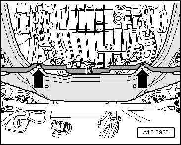
Note:

Gearbox must not be lowered any further as otherwise joint of propshaft and decoupling elements of exhaust system could be damaged.

 
A34-0521
  • ‒ → Unscrew heat shield for right drive shaft -arrow-.
 
N34-1208
  • ‒ → Unscrew connecting rod -2- of selector rod.
  • ‒ Screw out hexagon socket-head bolt of push rod -1-.

 
A26-0685
  • ‒ → Lay bare lambda probe wires at locations on gearbox marked with arrows.

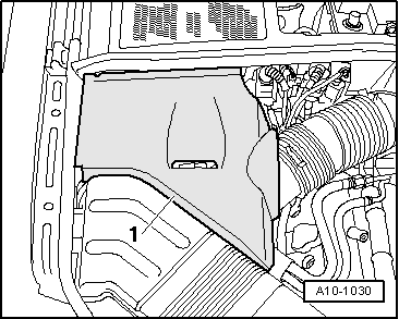
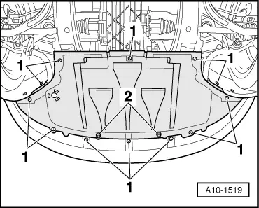
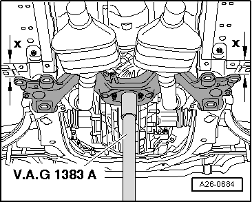
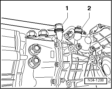
Note:

Illustration shows engine/gearbox assembly removed.

 
A24-0718
  • ‒ → Use special tool 3337 to screw out lambda probe -1-.

Installing

Install in reverse order, paying attention to the following:

Notes:

  • ◆ Thread of new lambda probe is coated with assembly paste which must not be allowed to ingress into openings in probe.
  • ◆ Re-attach all cable ties at same location on installation.
  • ◆ Secure all hose connections with standard hose clamps.

=> Parts List

  • ‒ Install subframe.

=> Running Gear, Front-wheel drive and four-wheel drive; Repair Group 40

  • ‒ Perform stress-free alignment of exhaust system.

=> Engine, Mechanics; Repair Group 26

Tightening torques

Component

Nm

Lambda probe to catalytic converter

55 1)

Push rod to gearbox

40

Connecting rod for selector rod to gearbox

23

    1)    If a lambda probe is to be re-used, grease thread only with hot bolt paste. This must not be allowed to ingress into openings in probe. Hot bolt paste

=> Parts List

Removing and installing lambda probe downstream of catalytic converter, bank 2 (left) > < Removing and installing lambda probe upstream of catalytic converter, bank 2 (left)