
A4 Mk2
| Exploded view of components |
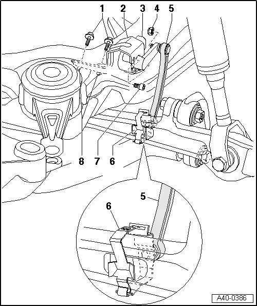
| 1 - | Hexagon bolt |
| q | 9 Nm |
| 2 - | Bracket |
| 3 - | Front left vehicle level sender -G78- |
| q | Is tested electrically via self-diagnosis |
| q | If malfunctions occur, follow “Guided Fault Finding” procedure using vehicle diagnostic, testing and information system -VAS 5051A- |
| q | Removing and installing → Anchor |
| 4 - | Self-locking nut |
| q | 10 Nm |
| q | Always renew if removed |
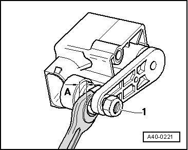
| 5 - | Coupling rod from front left vehicle level sender -G78- |
| q | Do not pull coupling rod off ball joint on vehicle level sender -G78- |
| 6 - | Retaining clip |
| q | Fastener of clip must face upwards at track control link and towards rear of vehicle |
| 7 - | Hexagon socket head bolt |
| q | 4 Nm |
| 8 - | Pop rivet nut |
|
|
|
 Note
Note
|
|
Note
|
|