audi Workshop Repair Guides

Audi Workshop Service and Repair Manuals

Removing and installing wheel bearing unit (bolted version) > < Servicing wheel bearing housing (steel) - four-wheel drive
Removing and installing wheel bearing with wheel bearing housing (steel) installed - four-wheel drive
Special tools and workshop equipment required
   
t  Engine and gearbox jack -V.A.G 1383 A- with universal gearbox support -V.A.G 1359/2-
  W00-0120
t  Foot pump with high-pressure hose -V.A.G 1389 A/1-
If there is a hand pump -V.A.G 1389/1- available in the dealership it can be converted to a foot-operated pump.
To do this, use the conversion set -V.A.G 1389/4-.
Special tools and workshop equipment required
  W00-0681
t  Hydraulic wheel bearing tool -V.A.G 1459B-
t  Hollow piston cylinder HKZ-15 with thrust piece (hydraulic) -E-0-204-T-
t  Pull rod -E-0-217+218-
t  Special nut -E-8-214-
t  Thrust piece -E-5-
  W00-0676
t  Supplementary set -V.A.G 1459 B/2-
t  Support -E-40-
t  Thrust piece -E-43-
t  Thrust sleeve -E-44-1-
–  Remove brake caliper, brake disc and splash plate. → Brake system; Rep. Gr. 46; Rear brakes type C38; Servicing brake caliper
–  Remove drive shaft → Chapter.
Place engine/gearbox jack -V.A.G 1383 A- underneath (danger of accident from parts dropping out when wheel hub and wheel bearing are pulled out).
  W00-0678
Pulling out wheel hub
–  Attach support -1-, hollow piston cylinder -2- with pull rod and special nut -3-.
–  Pull out wheel hub by actuating pump while holding tools steady.
1 -  Support E-40
2 -  Hollow piston cylinder HKZ-15
3 -  Special nut E-8-214 and pull rod
  A42-0265
Pulling out wheel bearing
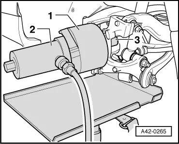
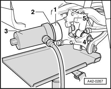
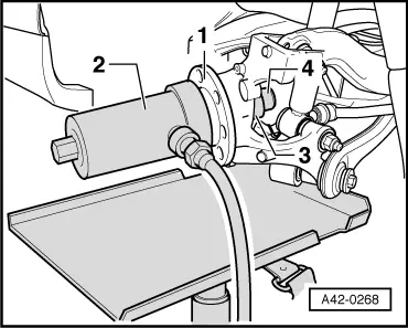
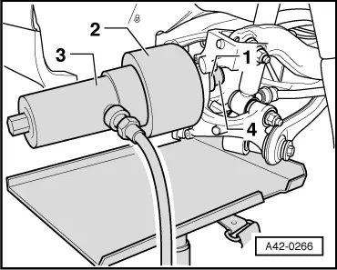
–  Set up thrust piece -1- with collar facing wheel bearing, thrust sleeve -2- with four stepped internal diameters towards wheel bearing housing and hollow piston cylinder -3- with pull rod and special nut -4-.
–  Pull out wheel bearing by actuating pump.
1 -  Thrust piece E-5
2 -  Thrust sleeve E-44-1
3 -  Hollow piston cylinder HKZ-15
4 -  Special nut E-8-214 and pull rod
  A42-0266
Pressing in wheel bearing
Installation position: The larger internal diameter of the wheel bearing faces outwards.
–  Set up wheel bearing -1-, thrust piece -2- (fit with collar in bearing) and hollow piston cylinder -3- with pull rod on wheel bearing housing.
–  Fit thrust piece -4- inside with chamfers facing wheel bearing housing and special nut -5-.
–  Press in wheel bearing by actuating pump.
1 -  Wheel bearing
2 -  Thrust piece E-14-1
3 -  Hollow piston cylinder HKZ-15
4 -  Thrust piece E-43
5 -  Special nut E-8-214 and pull rod
  A42-0267
Pressing in wheel hub
–  Fit wheel hub -1- and hollow piston cylinder -2- with pull rod on wheel bearing.
–  Fit thrust piece -3- from inside with collar facing special nut -4-.
–  Press in wheel hub by actuating pump.
1 -  Wheel hub
2 -  Hollow piston cylinder HKZ-15
3 -  Thrust piece E-5
4 -  Special nut E-8-214 and pull rod
Remaining installation steps are carried out in reverse sequence.
–  Install drive shaft → Chapter.
–  Install brake caliper, brake disc and splash plate. → Brake system; Rep. Gr. 46; Rear brakes type C38; Servicing brake caliper
  A42-0268

Removing and installing wheel bearing unit (bolted version) > < Servicing wheel bearing housing (steel) - four-wheel drive