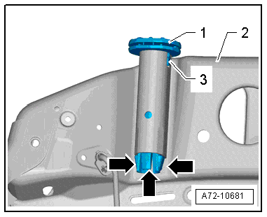
| Head restraint guide with release button: |

Note | t
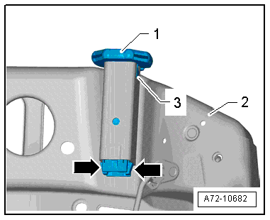
| When inserting head restraint guide -1-, observe correct positioning of lug -3- at backrest frame -2-. |
| t
| Make sure retaining tabs -arrows- engage properly with backrest frame. |
| Head restraint guide without and with release button (continued) |
Note | Make sure electrical connectors are fitted correctly (as far as stop) and engage audibly. |

WARNING | The battery must be connected with the ignition switched on. If pyrotechnic components (e.g. airbag or belt tensioner) are inexpertly repaired, this may result in unwanted triggering after connecting the battery. There must not be anyone in the vehicle while you are connecting the battery. |
|
Note | If the airbag warning lamp -K75- indicates a fault following installation, you must interrogate, erase and then re-interrogate the event memory → Vehicle diagnostic tester. |
|
|
|