audi Workshop Repair Guides

Audi Workshop Service and Repair Manuals

Covers and padding on rear seats > < Exploded view of cover and padding for head restraint
Removing and installing cover and padding for head restraint with slide-in locking mechanism
Special tools and workshop equipment required
   
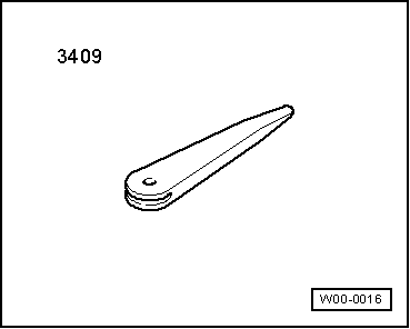
t  Removal wedge -3409-
Removing
  WARNING
t  Observe safety regulations for pyrotechnic components → Chapter.
t  Before handling pyrotechnic components (e.g. unplugging the electrical connector) the mechanic must discharge static electricity by briefly touching the door striker plate, or similar.
–  Remove head restraint:
t  → Chapter „Removing and installing head restraint with slide-in locking mechanism“.
t  → Chapter „Removing and installing head restraint (with electric adjustment)“.
  W00-0016
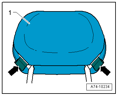
Opening fasteners (side)
–  Open side fasteners -arrows- on cover -1-.
  A74-10234
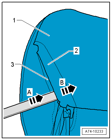
–  Insert removal wedge -3409- or a flat screwdriver in between cover fastening -1- in direction of -arrow A-.
–  Apply tension to bottom U-profile -3- in direction of -arrow B-.
–  Pull upper side of cover out of U-profile with flat profile -2-.
  A74-10233
Opening main fastener
–  Insert removal wedge -3409- or a flat screwdriver in between cover fastening.
–  Apply tension to bottom U-profile -1- in direction of -arrow A-.
–  Pull upper side of cover out of U-profile -1- with flat profile -2-.
  Note
To take out padding cover must be fully open.
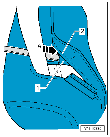
  A74-10235
–  Take padding -1- out of cover -2-.
Installing
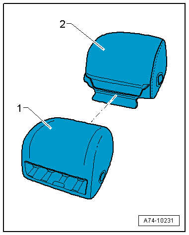
–  Insert padding -1- in cover -2-, making sure that it fits correctly.
–  Insert head restraint mounting bracket in padding with cover.
  A74-10231
Closing main fastener
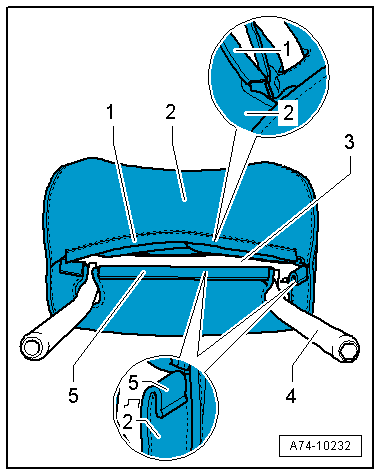
–  Turn over upper flat profile -1- of cover -2-.
–  Insert edge of fabric into U-profile -5- with flat profile.
Closing fasteners (side)
–  The procedure for closing the side fasteners is similar to that for closing the main fastener.
Continuation after closing main fastener and side fasteners
–  Align cover and profiles using a needle or another sharp object.
–  Make sure cover is positioned on padding -3- without creases or seam marks.
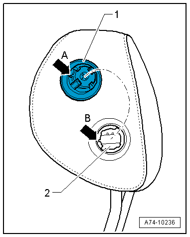
–  For head restraint with manual adjustment, install release button for height adjustment.
–  Insert release button through cover and padding into mounting bracket -4- for head restraint.
–  When doing so, pay attention to locating pin for release button/head restraint mounting bracket.
  A74-10232
–  Lug -arrow A- on release button -1- must coincide with slit -arrow B- in button mounting of head restraint mounting bracket -2-.
–  Clip release button into mounting bracket for head restraint.
  WARNING
t  Observe safety regulations for pyrotechnic components → Chapter.
t  Before handling pyrotechnic components (e.g. plugging in the electrical connector) the mechanic must discharge static electricity by briefly touching the door striker plate, or similar.
Perform remaining installation steps in reverse order of removal; observe the following:
  Note
Make sure electrical connectors are fitted correctly (as far as stop) and engage audibly.
  WARNING
The battery must be connected with the ignition switched on. If pyrotechnic components (e.g. airbag or belt tensioner) are inexpertly repaired, this may result in unwanted triggering after connecting the battery. There must not be anyone in the vehicle while you are connecting the battery.
–  With ignition switched on, connect battery earth wire → Electrical system; Rep. gr.27.
  Note
If the airbag warning lamp -K75- indicates a fault following installation, you must interrogate, erase and then re-interrogate the event memory → Vehicle diagnostic tester.
  A74-10236

Covers and padding on rear seats > < Exploded view of cover and padding for head restraint