audi Workshop Repair Guides

Audi Workshop Service and Repair Manuals

Removing and installing loudspeaker mounting > < Removing and installing retaining frame for instrument cluster
Removing and installing dash panel
Removing
–  Move steering wheel down and to rear as far as possible, using full range of steering column adjuster.
–  Move seats to rearmost position and backrests to 45° position.
  WARNING
t  Observe safety regulations for pyrotechnic components → Chapter.
t  For correct allocation of dash panel and airbag refer to → Electronic parts catalogue.
–  Switch on ignition.
–  With ignition switched on, disconnect battery earth wire → Electrical system; Rep. gr.27.
–  Remove airbag (driver side) → Rep. gr.69.
–  Remove steering wheel → Rep. gr.48.
–  Remove trim cover for instrument cluster → Chapter.
–  Remove dash panel cover (driver side) → Chapter.
–  Unplug electrical connector for light switch → Electrical system; Rep. gr.96.
–  Equipment version with headlight range control: Unplug electrical connector at headlight range control regulator -E102- → Electrical system; Rep. gr.96.
–  Remove side dash panel vent → Chapter.
–  Remove cover for MMI screen:
t  → Chapter „Removing and installing cover for MMI screen - up to model year 2011“.
t  → Chapter „Removing and installing cover for MMI screen - from model year 2012 onwards“.
–  Remove MMI screen → Rep. gr.91.
–  Remove instrument cluster → Electrical system; Rep. gr.90.
–  Unplug electrical connector at entry and start authorisation switch → Electrical system; Rep. gr.94.
–  Remove dash panel vent (centre) → Chapter.
–  Remove radio/navigation system → Rep. gr.91.
–  Remove Climatronic control unit -J255- → Rep. gr.87.
–  Remove control unit for front display and information control panel -J523- → Rep. gr.91.
–  Remove centre console → Chapter.
–  Remove glove box → Chapter.
  WARNING
Before handling pyrotechnic components (e.g. unplugging the electrical connector) the mechanic must discharge static electricity by briefly touching the door striker plate, or similar.
–  Unplug electrical connectors for airbag (front passenger side) → Chapter.
–  Equipment version with loudspeaker: Remove mid-range and treble loudspeaker in centre of dash panel → Rep. gr.91.
–  Remove sunlight penetration photosensor -G107- → Rep. gr.87.
–  Equipment version with loudspeaker: Remove mid-range and treble loudspeaker (side) from dash panel → Rep. gr.91.
–  Remove A-pillar trim panels (top) → Chapter.
–  Remove brackets for glove box → Chapter.
–  Disengage brace at dash panel and detach.
   
–  Remove bolts -1- for dash panel at top left and right in area of A-pillar.
–  Unscrew bolts -2- for dash panel at bottom left and right.
–  Remove bolts -arrows- for air ducts on left and right of dash panel.
  A70-10608
–  Remove bolts -1- for dash panel at central tube for dash panel (centre).
–  Unscrew bolts -2- for dash panel at central tube for dash panel (right-side).
–  Unscrew bolt -3- for dash panel at central tube for dash panel (left-side).
  Note
  A70-10609
A second mechanic is required for detaching the dash panel.
–  Carefully detach dash panel -1- from central tube for dash panel towards rear -arrows A-.
–  At the same time, disengage dash panel at bottom of retainer -2--arrow B-.
–  Take dash panel out of passenger compartment and set it down on a soft surface.
Installing
Installation is carried out in the reverse order; note the following:
  WARNING
For correct allocation of dash panel and airbag refer to → Electronic parts catalogue.
–  Place dash panel in position and route electrical connectors for sunlight penetration photosensor -G107- and loudspeakers through openings in dash panel.
  A70-10666
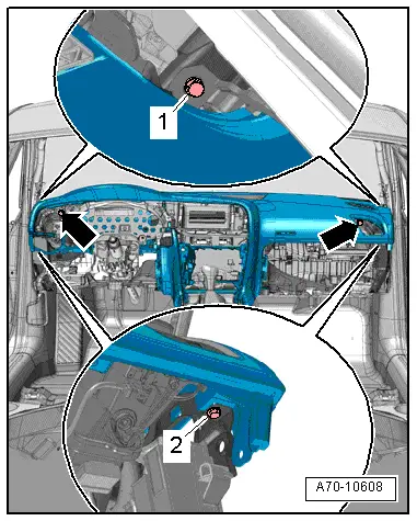
–  Check whether a rubber buffer -3- has been fitted on each of the clips -2- at the lower windscreen frame.
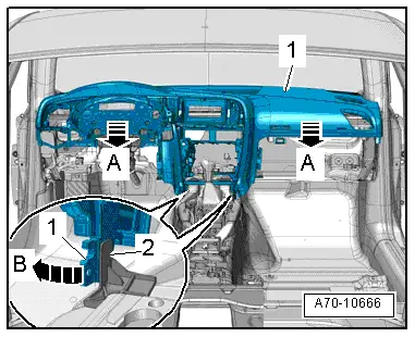
–  When inserting dash panel -1-, make sure clips engage in box-shaped sections on underside of dash panel.
  WARNING
t  Observe safety regulations for pyrotechnic components → Chapter.
t  Before handling pyrotechnic components (e.g. plugging in the electrical connector) the mechanic must discharge static electricity by briefly touching the door striker plate, or similar.
  Note
Make sure electrical connectors are fitted correctly (as far as stop) and engage audibly.
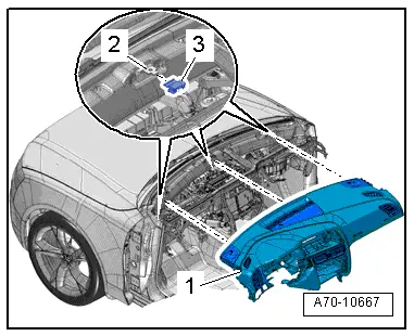
–  Align dash panel and tighten bolts.
  WARNING
The battery must be connected with the ignition switched on. If pyrotechnic components (e.g. airbag or belt tensioner) are inexpertly repaired, this may result in unwanted triggering after connecting the battery. There must not be anyone in the vehicle while you are connecting the battery.
–  With ignition switched on, connect battery earth wire → Electrical system; Rep. gr.27.
  Note
If the airbag warning lamp -K75- indicates a fault following installation, you must interrogate, erase and then re-interrogate the event memory → Vehicle diagnostic tester.
Tightening torques → Chapter, → Chapter
  A70-10667

Removing and installing loudspeaker mounting > < Removing and installing retaining frame for instrument cluster