
A4 Mk3
 Note
Note
|
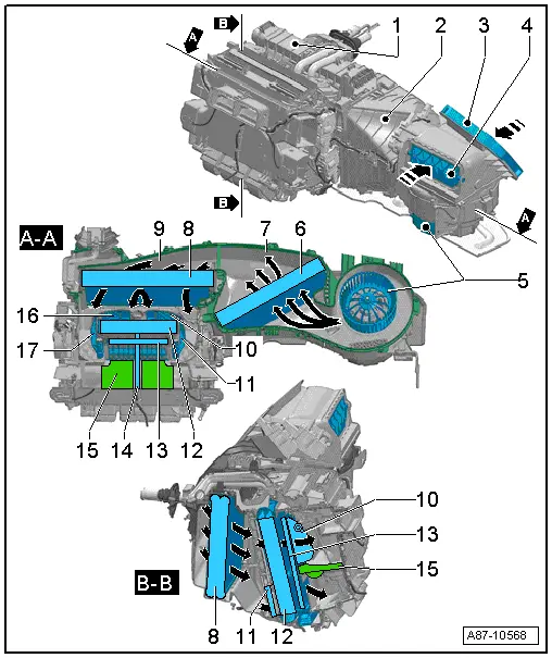
| 1 - | Air conditioning unit |
| q | Different versions depending on air conditioner model („Deluxe“ and „Basic“) → Chapter and → Electronic parts catalogue |
| 2 - | Air intake box |
| 3 - | Fresh air intake |
| q | The air is drawn in from the plenum chamber → Chapter. |
| 4 - | Intake for air from passenger compartment (in air recirculation mode) |
| q | When the air recirculation flap is open, the air is drawn in beneath the glove compartment from the passenger's footwell |
| q | This illustration shows the air recirculation flap in „closed“ position. |
| 5 - | Fresh air blower -V2- |
| 6 - | Dust and pollen filter |
| q | There are different versions of the dust and pollen filter (without and with activated charcoal filter element) → Chapter and → Electronic parts catalogue. |
| 7 - | Bottom part of air intake box (with fitted components) |
| q | This illustration shows an „A - A“ sectional view of the air intake box. |
| 8 - | Evaporator |
| 9 - | Bottom part of air conditioning unit (with fitted components) |
| q | This illustration shows an „A - A“ sectional view of the air conditioning unit. |
| 10 - | Temperature flap for front right vents |
| q | This illustration shows the temperature flap in „heating“ position. |
| q | With the „Deluxe“ version of the air conditioner, the front right and left temperature flaps are actuated by one control motor each. The two temperature flaps for the rear vents are inter-linked by way of a connecting rod and actuated by a further control motor → Chapter. |
| q | With the „Basic“ version of the air conditioner, the front temperature flaps and the temperature flap for the rear footwell vents are inter-linked by way of the shaft. The shafts of the right and left temperature flaps are inter-linked by way of a connecting rod and actuated by one control motor → Chapter. |
| q | Temperature flaps in left and right heater housing → Chapter |
| 11 - | Temperature flap for rear right vents |
| q | This illustration shows the temperature flap in „cooling“ position. |
| q | Notes on actuation of the temperature flaps → Item |
| 12 - | Heating system heat exchanger |
| q | Removing and installing heat exchanger with air conditioning unit fitted → Chapter |
| q | Different foam seals affixed depending on air conditioner model („Deluxe“ and „Basic“) → Chapter |
| 13 - | Supplementary air heater element -Z35- / honeycomb element |
| The supplementary air heater element -Z35- is fitted on vehicles with a diesel engine and vehicles with certain petrol engines → Chapter. |
| Vehicles with a petrol engine (with no supplementary air heater element -Z35-) are fitted with a honeycomb element as spacer element in the unused space (this ensures identical flow conditions in the air conditioning unit with and without the supplementary air heater element -Z35-). |
| q | If, on vehicles with a diesel engine, an auxiliary heater fitted as optional extra is actuated as supplementary heater, there is no supplementary air heater element -Z35- but rather only a honeycomb element (introduction not yet finalised) → Chapter. |
| q | Different foam seals affixed depending on air conditioner model („Deluxe“ and „Basic“) → Chapter |
Note| t | In Model Year 2009, a modified version of the supplementary air heater element -Z35- (slightly slimmer heating element design) was gradually introduced. Pay attention the correct version and assignment → Electronic parts catalogue. |
| t | As of Model Year 2010, petrol engines designed for operation with bioethanol are being gradually introduced (Flex Fuel Vehicle). These engines are currently also fitted with a supplementary air heater element -Z35- → Chapter. |
| t | Vehicles with a high-voltage system (hybrid vehicles) and petrol engine are currently also fitted with a supplementary air heater element -Z35- → Chapter. |
| 14 - | Partition |
| q | Only fitted on vehicles with an air conditioner of „Deluxe“ type (not provided with „Basic“ version, in this case only one temperature setting is possible for all vents). |
| q | Separates the flow of air to the left and right vents on the „Deluxe“ version; prerequisite for different air outlet temperatures. The temperature of the air emerging depends on the setting of the corresponding temperature flaps → Item. |
| 15 - | Partition |
| q | Only fitted on vehicles with an air conditioner of „Deluxe“ type (not provided with „Basic“ version, in this case only one temperature setting is possible for all vents). |
| q | With the „Deluxe“ version, this separates the air duct to the front and rear vents and is necessary to permit different air outflow temperatures at the front and rear (depending on the position of the corresponding temperature flap → Item). |
| 16 - | Temperature flap for rear left vents |
| q | This illustration shows the temperature flap in „heating“ position. |
| q | Notes on actuation of the temperature flaps → Item |
| 17 - | Temperature flap for front left vents |
| q | This illustration shows the temperature flap in „cooling“ position. |
| q | Notes on actuation of the temperature flaps → Item |