audi Workshop Repair Guides

Audi Workshop Service and Repair Manuals

Removing and installing left heater housing (with temperature flaps) > < Dismantling and assembling left mounting plate with control motors V108 and V110
Removing and installing left temperature flap control motorV158
Removing and installing left temperature flap control motor -V158-
  Note
t  The left temperature flap control motor -V158- is only fitted on vehicles with an air conditioner of the „Deluxe“ type.
t  At present all the control motors on this vehicle are identical. During basic setting, control motor assignment and adaption are implemented on the basis of the arrangement in the series connection of the wiring. If the sequence is not as specified, the matching of the control motors and thus flap control will not be correct → Chapter „Block diagram of air conditioner control motors“.
t  Different versions of the levers and connecting elements are fitted at the air conditioning unit depending on the production period → Chapter and → Electronic parts catalogue.
Removing
–  Switch on the ignition.
–  Move the driver's seat to the rearmost position.
–  Set the air outflow direction for the driver and front passenger side to the footwell vents on the air conditioner operating and display unit, Climatronic control unit -J255-.
  Note
   
In the „air to footwell vents“ setting, the defroster flap control motor -V107- moves the connecting rod -A- to a position in which the bolt -B- is accessible. If the defroster flap control motor -V107- does not move the connecting rod -A- to the required position, it may be necessary to remove the control motor → Chapter.
–  Switch off the ignition.
–  Remove the storage compartment beneath the dash panel on the driver side → General body repairs, interior; Rep. gr.70.
–  Remove the left (driver side) footwell vent → Chapter.
–  Remove the steering column → Running gear; Rep. gr.48.
–  Remove the pedal cluster and accelerator pedal module → Brakes - mechanism; Rep. gr.46 and → Fuel supply system; Rep. gr.20.
  A87-10506
–  Remove the left centre vent control motor -V110--B- → Chapter.
  A87-10495
–  Mark the connector -C- to prevent interchange.
–  Unplug the connector -C-.
–  Remove the bolts -B-.
–  Release the pin -D- (at the holder of the control motor -E-) from the toothed segment -F- (of the temperature flap shaft) and remove the holder -E- (with the control motor) in arrow direction.
  A87-10506
–  Remove the bolts -A- and separate the control motor -B- from the holder -D-.
–  Detach the gear wheel -C- from the shaft -D- of the control motor.
  Note
t  On right-hand drive vehicles as opposed to left-hand drive vehicles, the temperature flap is not actuated directly by way of the gear wheel -C- attached to the shaft -D- of the control motor.
  A87-10507
t  On right-hand drive vehicles, the temperature flap is not actuated by way of the gear wheel -A- attached to the shaft of the control motor -C-. These vehicles are fitted with a second gear wheel -B- (the diameter of the gear wheels -A- and -B- is somewhat smaller than that of the single gear wheel with the left-hand drive version). The gear wheel -B- then actuates the temperature flap via the toothed segment inserted in the shaft.
Installing
Install in reverse order; paying attention to the following:
  A87-10575
–  Attach the gear wheel -C- to the shaft -E- of the control motor -B-.
  Note
The control motor has no stop. The gear wheel -C- can thus be attached in any position to the shaft of the control motor.
  A87-10507
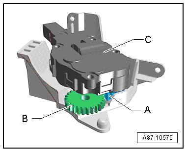
–  By turning in arrow direction, move the toothed segment -E- (of the temperature flap shaft) as far as it will go to the position shown.
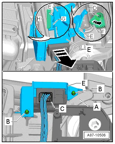
–  Insert the guide -G- (at the holder -E- with the control motor) in the mount -H- (at the air conditioning unit).
–  Slide the holder -E- in the direction opposite to the arrow towards the toothed segment -F- and insert the pin -D- (at the holder of the control motor -E-) in the toothed segment -F- (of the temperature flap shaft).
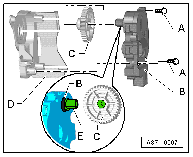
  Note
The control motor and the gear wheel -J- have no stop. The gear wheel -J- and the toothed segment -F- (of the temperature flap shaft) can thus be assembled in any position.
–  Fit the bolts -B-.
–  Plug in the connector -C-.
–  Lay the wiring harness such that it cannot come into contact with moving components (e.g. lever).
–  Re-install all the other parts removed in reverse order.
–  Switch on the ignition.
–  Perform air conditioner basic setting and final control diagnosis → "Guided fault-finding" function of vehicle diagnostic, testing and information system VAS 5051.
  Note
t  The control motors on this vehicle are equipped with electronics. A new control motor only learns its position at the air conditioning unit in the course of basic setting and can then be actuated by the air conditioner operating and display unit, Climatronic control unit -J255- (all control motors are identical at present) → "Guided fault-finding" function of vehicle diagnostic, testing and information system VAS 5051.
t  During basic setting, control motor assignment and adaption are implemented on the basis of the arrangement in the series connection of the wiring. If the sequence is not as specified, the matching of the control motors and thus flap control will not be correct → Chapter (block diagram of air conditioner control motors).
–  Interrogate the event recorder of the air conditioner operating and display unit, Climatronic control unit -J255- and erase any faults displayed → "Guided fault-finding" function of vehicle diagnostic, testing and information system VAS 5051.
  A87-10506

Removing and installing left heater housing (with temperature flaps) > < Dismantling and assembling left mounting plate with control motors V108 and V110