audi Workshop Repair Guides

Audi Workshop Service and Repair Manuals

Checking actuation of air conditioner compressor regulating valveN280 > < Detaching electrically driven air conditioner compressor from holder/attaching
Checking activation signal for air conditioner compressor regulating valveN280
Checking activation signal for air conditioner compressor regulating valve -N280-
  Note
t  The following describes testing of a „Denso“ air conditioner compressor of type „6 SEU 14“. Checking is to be performed in the same manner for vehicles with a different type of compressor or from a different manufacturer.
t  In the following, checking is described for a vehicle with a 6-cyl. TDI engine. The procedure may differ for vehicles with a different engine (4, 6 or 8-cyl. engine).
t  Not fitted with an electrically driven air conditioner compressor → Chapter
Preparation
–  Switch off the ignition.
–  Remove the front noise insulation → General body repairs, exterior; Rep. gr.50.
Test sequence
   
–  Unplug the connector -B- at the air conditioner compressor regulating valve -N280--A-.
–  Use an adapter cable from the adapter set -V.A.G 1594 C- to re-establish the connection between the connector -A- and the connector -B- at the air conditioner compressor regulating valve -N280-.
  Note
t  The air conditioner compressor regulating valve -N280- is actuated by the onboard supply control unit -J519- when requested by the air conditioner operating and display unit, Climatronic control unit -J255- → "Guided fault-finding" function of vehicle diagnostic, testing and information system VAS 5051 and → Current flow diagrams, Electrical fault finding and Fitting locations.
  A87-10293
t  The top illustration shows an air conditioner compressor on which the connector -A- to the vehicle wiring harness is plugged in directly at the air conditioner compressor regulating valve -N280- (connector -B-). Depending on the version of the air conditioner compressor, the connector -B- may also be provided with a short wire.
t  Actuation of the air conditioner compressor regulating valve -N280- is displayed in the measured value block of the onboard supply control unit -J519-. The maximum control current is governed by the version of the operating and display unit, Climatronic control unit -J255- → "Guided fault-finding" function of vehicle diagnostic, testing and information system VAS 5051 and → Current flow diagrams, Electrical fault finding and Fitting locations.
t  The measured current flowing via the air conditioner compressor regulating valve -N280- is displayed in the measured value block of the air conditioner operating and display unit, Climatronic control unit -J255- and in the measured value block of the onboard supply control unit -J519- → "Guided fault-finding" function of vehicle diagnostic, testing and information system VAS 5051.
t  If the required actual current does not flow via the air conditioner compressor regulating valve -N280-, check the positive and earth connections of the onboard supply control unit -J519- and the wiring between -J519- and -N280- on the basis of the current flow diagram for open circuit, contact resistance and interchange → Current flow diagrams, Electrical fault finding and Fitting locations.
  A87-10009
t  An adapter lead may also be made for this test. This requires, for example, one connector -A- and -B- each (with part number 1J0 973 702 and 1J0 973 802 and the corresponding plug contacts), two commercially available sockets for banana plugs -C- and two wires with a cross section of 0.5 mm2.
  A87-0389
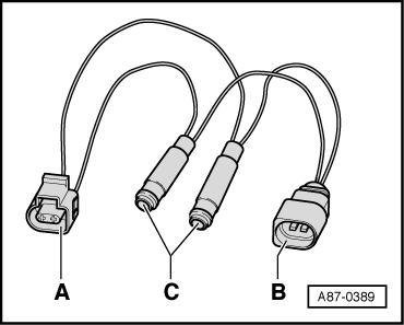
–  Connect the probe -VAS 5051/8- to the adapter leads.
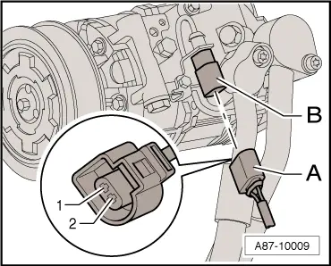
–  Test lead (signal wire) to contact -2- of connector -B-.
–  Test lead (screen, earth) to contact -1- of connector -B-.
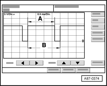
–  On vehicle diagnostic, testing and information system -VAS 5051/-, set testing mode DSO (Digital Storage Oscilloscope).
–  Select the settings 5 V / div DC, 0.5 ms/div (5 V DC and 0.5 milliseconds per unit).
–  Start the engine.
–  Set the temperature on the air conditioner operating and display unit, Climatronic control unit -J255- to maximum cooling output.
–  On the air conditioner operating and display unit, Climatronic control unit -J255- press the „AC“ button (with air conditioner compressor ON indicator) to activate and deactivate the air conditioner compressor regulating valve -N280-.
The display on the oscilloscope screen will be as follows depending on the setting on the air conditioner operating and display unit, Climatronic control unit -J255-:
–  In „OFF“ or „AC off“ mode (lamp in „AC“ button not lit), no square-wave signal (air conditioner compressor regulating valve -N280- is not actuated).
  A87-10293
–  In „Auto“ and „AC on“ mode (lamps in buttons light) and with the temperature set to maximum cooling output, square-wave signal with a pulse width -A- between 75 % and 100 % (the regulating valve is actuated).
  Note
t  The illustration shows a signal with a signal ratio of approx. 80 %.
t  The pulse width -A- is governed by the required cooling output and the electrical system voltage etc. (over the width of area -A- the current is controlled via the air conditioner compressor regulating valve -N280- by the onboard supply control unit -J519- on the basis of the request from the air conditioner operating and display unit, Climatronic control unit -J255-).
t  The signal distance -B- is always 2 milliseconds (corresponding to a frequency of 500 hertz).
t  The signal ratio is derived from the ratio of pulse width -A- to signal distance -B-.
–  The setting on the air conditioner operating and display unit, Climatronic control unit -J255- and the measured ambient influences govern the pulse width of the square-wave signal (signal ratio between 100 % and greater than 30 %, the air conditioner compressor regulating valve -N280- is actuated such that the compressor output required to obtain the specified temperatures is achieved).
  Note
t  In „Auto“ and „AC on“ mode (lamps in buttons light) and with „Lo“ temperature setting, the air conditioner compressor regulating valve -N280- is actuated such that the maximum permissible current of approx. 0.65 A flows via -N280- (maximum compressor output).
t  In control mode, the actuation time is governed by the required cooling output and the vehicle electrical system voltage, for example. It is however always of sufficient duration to achieve a mean current of 0.3 A.
t  Checking actuation of air conditioner compressor regulating valve -N280- → Chapter
  A87-0374

Checking actuation of air conditioner compressor regulating valveN280 > < Detaching electrically driven air conditioner compressor from holder/attaching