audi Workshop Repair Guides

Audi Workshop Service and Repair Manuals

Checking activation signal for air conditioner compressor regulating valveN280 > < Detaching air conditioner compressor from holder/attaching (vehicles with 6-cyl. TDI engine)
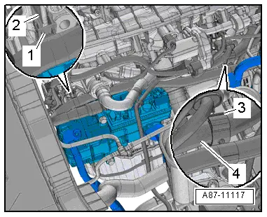
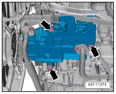
Detaching electrically driven air conditioner compressor from holder/attaching
Fitted on vehicles with a high-voltage system (hybrid vehicles)
For all work on vehicles with a high-voltage system, pay attention to the additional warnings for such vehicles → Chapter and → Electrical system; Rep. gr.93.
  WARNING
Danger from unexpected engine starting
When performing general work on vehicles with a high-voltage system, switch off the ignition and remove the ignition key from the passenger compartment.
  WARNING
Working on vehicles with high-voltage wiring:
l  Do not support yourself or tools on high-voltage wiring or associated components --> this can damage the insulation.
l  High-voltage wiring must not be excessively bent or kinked --> this can damage the insulation.
l  The round high-voltage connectors are colour-coded with an external coloured ring and are provided with mechanical coding or guide lugs. It is important to observe this coding when joining up the round high-voltage connectors, otherwise the connectors can be damaged.
  DANGER!
Risk of fatal injury if high-voltage components are damaged.
Observe the following when working in the vicinity of high-voltage components or wiring:
t  It is not permitted to use cutting or forming tools, other sharp-edged tools or heat sources such as welding, brazing, soldering, hot air or thermal bonding equipment.
t  Before starting work, visually inspect the high-voltage components in the areas involved.
t  Before working in the engine compartment, visually inspect the power electronics -JX1-, electric drive motor -V141-, air conditioner compressor -V470- and high-voltage wiring.
t  Before working on the vehicle underbody, visually inspect the high-voltage wiring and covers.
t  Before working on the rear section of the vehicle, visually inspect the high-voltage wiring and the electro-box with the maintenance connector for high-voltage system - TW -.
t  Visually inspect all potential equalisation lines.
Check the following when making the visual inspection:
t  There must be no external damage on any component.
t  The insulation of the high-voltage wiring and potential equalisation lines must not be damaged.
t  There must be no unusual deformation of the high-voltage wiring.
t  All high-voltage components must be identified by a red warning sticker.
  Note
t  With control unit for air conditioning compressor -J842- and electrical air conditioner compressor -V470-
t  The electric motor of the air conditioner compressor is supplied with power by the power and control electronics for electric drive -JX1-.
t  The control unit for air conditioning compressor -J842- integrated into the air conditioner compressor regulates the speed and thus the output of the air conditioner compressor (electrical air conditioner compressor -V470-) on the basis of the request received via the data bus → Vehicle diagnostic tester, „Guided fault-finding“ function for air conditioner and battery regulation
t  The electrically driven air conditioner compressor is not fitted with an air conditioner compressor regulating valve -N280-. The output of the air conditioner compressor is regulated externally by way of the air conditioner compressor speed → Current flow diagrams, Electrical fault finding and Fitting locations and → Vehicle diagnostic tester, „Guided fault-finding“ function for air conditioner and battery regulation.
t  At present, the electrically driven air conditioner compressor operates on the principle of a spiral-type supercharger.
t  The control unit for air conditioning compressor -J842- and the electrical air conditioner compressor -V470- form one component and cannot be separated at present.
As work on the high-voltage system is required for the following sequence of operations, the high-voltage system has to be isolated from the supply → Chapter, → Electrical system; Rep. gr.93 and attention is to be paid to the „General warnings for working on high-voltage system“ → Electrical system; Rep. gr.93
  Note
t  On vehicles with a 4-cyl. engine, the air conditioner compressor can be detached from the holder and re-attached without opening up the refrigerant lines.
t  
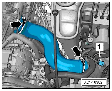
Do not drain the refrigerant circuit when detaching from the holder. Do not detach refrigerant hoses and refrigerant lines from the air conditioner compressor.
t  Do not unfasten the refrigerant lines and the corresponding clamps.
t  
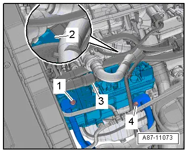
Leave the high-voltage system cable connected to the air conditioner compressor. Do not release the high-voltage system connector at the air conditioner compressor.
t  After detaching the air conditioner compressor, secure it with a piece of wire for example to the vehicle. Do not leave it suspended from the refrigerant lines.
t  Different air conditioner compressors may be fitted depending on the engine and country version. → Electronic parts catalogue
Detaching
As work on the high-voltage system is required for the following sequence of operations, the high-voltage system has to be isolated from the supply → Chapter, → Electrical system; Rep. gr.93 and attention is to be paid to the „General warnings for working on high-voltage system“ → Electrical system; Rep. gr.93
–  Switch off the ignition.
–  Isolate the high-voltage system from the supply → Electrical system; Rep. gr.93
Isolation of high-voltage system from supply
  DANGER!
High voltage can cause fatal injury.
Danger of severe or fatal injuries from electric shock.
t  Voltage levels in the high-voltage system constitute a safety hazard.
t  For reasons of safety, persons with life-preserving or other electronic medical devices in or on their body must not perform any work on the high-voltage system. Such medical devices include internal analgesic pumps, implanted defibrillators, pacemakers, insulin pumps and hearing aids.
t  The high-voltage system may only be de-energised by a suitably qualified person (Audi high-voltage technician).
t  It must be definitely confirmed that the high-voltage system is de-energised. The system may only be de-energised using the vehicle diagnostic tester via „Guided Fault Finding“.
t  The qualified person (Audi high-voltage technician) confirms that the system is de-energised and uses the locking cap -T40262- to ensure that the system cannot be re-energised. The ignition key and the maintenance connector for high-voltage system - TW - should then be stored in a safe place by the qualified person.
t  The qualified person (Audi high-voltage engineer) attaches signs to mark the vehicle accordingly.
  Note
t  Isolation of high-voltage system from supply:
t  Connect the vehicle diagnostic tester
t  Select Guided fault-finding mode
t  Use the Go to key to consecutively select the following menu items
t  Function/component list
t  Body
t  Electrical system
t  Systems with self-diagnosis capability
t  8C - Hybrid battery management -J840
t  8C - Hybrid battery management, functions
t  51 - Isolation of high-voltage system from supply (Rep. Gr. 93)
–  Detach the engine cover → Rep. gr.24.
   
–  Unfasten the hose clamps -arrows- and detach the air hose.
  Note
-Item 1- can be ignored
  A21-10302
–  Lay bare the high-voltage system connector -3- at the engine.
–  Unplug the connector -2- (for low voltage at the air conditioner compressor).
  Note
-Items 1, 4- can be ignored.
  A87-11073
–  Screw out the air conditioner compressor bolts -arrows-.
  A87-11074
–  Detach the air conditioner compressor -A- and swivel it to the left away from the engine as far as possible without kinking and straining the cable of the high-voltage system -C- or the refrigerant hoses.
  Caution
Risk of damaging cable or connector of high-voltage system
t  Take care not to twist or bend the connector of the high-voltage system -B-.
t  Take care not to twist, strain, kink or bend the cable of the high-voltage system -C-.
–  Attach the air conditioner compressor to the vehicle (e.g. with a piece of wire) such that neither the high-voltage system cable nor the refrigerant hoses are kinked or strained.
  Caution
Risk of damage to high-voltage system cable or refrigerant lines and hoses.
Take care not to strain, kink or bend refrigerant lines and hoses.
  Note
If the air conditioner compressor cannot be swivelled far enough away from the engine, the compressor unit must be removed → Chapter.
Attaching
Install in reverse order, paying attention to the following:
t  Prior to installation, check the air conditioner compressor and holder attachment points. The contact surfaces must be clean and free from rust and grease. If this is not the case, treat the contact surfaces accordingly with the contact surface cleaning set -VAS 6410- → Electrical system general information; Rep. gr.93 .
  Note
t  After installing the air conditioner compressor and then filling the refrigerant circuit, first start up the electrically driven air conditioner compressor removed by way of the „Compressor run-in“ function of the basic setting routine. Otherwise, the air conditioner compressor may be damaged if refrigeration oil has accumulated in the compression chamber of the air conditioner compressor on account of inappropriate storage prior to installation → Chapter and → Vehicle diagnostic tester, „Guided fault-finding“ function for air conditioner and battery regulation
t  Electrically driven air conditioner compressors are only to be actuated with the refrigerant circuit charged. Running the air conditioner compressor with the refrigerant circuit empty could lead to compressor damage → Vehicle diagnostic tester, „Guided fault-finding“ function for air conditioner and battery regulation.
  A87-11249
–  Tighten bolts -arrows- (tightening torque: 25 Nm).
–  Plug in the connector for the electrical system.
  Note
t  After attaching the air conditioner compressor, check the routing of the refrigerant lines. They must be inserted in the holders provided (if fitted, depends on engine).
t  Check the refrigerant lines and the corresponding holders for adequate clearance with respect to the other components, ensuring a sufficient distance between the belt, holder and pulley.
  A87-11074
–  Attach the high-voltage system cable at the specified positions on the engine.
–  Secure the clip -1- at the engine -2- and the holder -3- at the wiring harness -4- as shown in the illustration.
–  Fit the air hoses with screw-type clamps → Engine, mechanics; Rep. gr.21.
–  Re-install the remaining components removed.
–  Re-establish the high-voltage system supply → Electrical system; Rep. gr.93
Re-activation of high-voltage system
  DANGER!
Potentially fatal high voltage
Risk of fatal or serious injury from electric shocks
t  High voltage at high-voltage system!
t  For safety reasons, work on the high-voltage system is not to be performed by persons wearing electronic/medical life and health-preserving devices in or on the body. Life and health-preserving devices include internal painkiller pumps, implanted defibrillators, pacemakers, insulin pumps and hearing aids.
t  The high-voltage system is only to be re-activated by an appropriately qualified person (Audi high-voltage engineer).
t  Re-activation is to be determined solely by way of the Vehicle diagnostic tester employing the „Guided fault-finding“ routine.
t  The qualified person (Audi high-voltage engineer) re-activates the vehicle.
t  The qualified person (Audi high-voltage engineer) attaches signs to mark the vehicle accordingly.
  Note
t  High-voltage system re-activation:
t  Connect the vehicle diagnostic tester
t  Select Guided fault-finding mode
t  Use the Go to key to consecutively select the following menu items
t  Function/component list
t  Body
t  Electrical system
t  Systems with self-diagnosis capability
t  8C - Hybrid battery management -J840
t  8C - Hybrid battery management, functions
t  51 - Re-activation of high-voltage system (Rep. Gr. 93)
–  Switch on the ignition.
–  Interrogate the event recorder of the operating and display unit, Climatronic control unit -J255- and the control unit for air conditioning compressor -J842- and erase any faults displayed → "Guided fault-finding" function of vehicle diagnostic tester.
  A87-11117

Checking activation signal for air conditioner compressor regulating valveN280 > < Detaching air conditioner compressor from holder/attaching (vehicles with 6-cyl. TDI engine)