| –
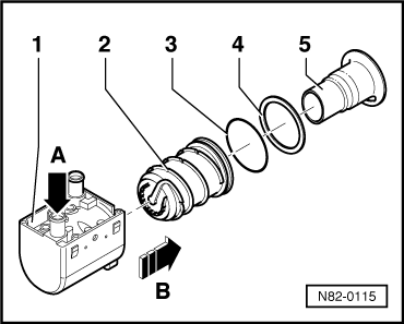
| Pull the burner element -5- out of the heat exchanger -2-. |
| Install in reverse order; paying attention to the following: |

Note | t
| Before installing the burner element -5-, replace the moulded gasket -4- (between the burner element and heater). |
| t
| If the burner element is defective, also replace the glow plug for heater -Q9-. |
| t
| Check the burner element. In the event of a defective glow plug for heater -Q9-, also replace the burner element if deposits have formed in it which affect heating operation and cannot be removed with workshop equipment. |
| t
| This illustration shows a burner element -5- with round connection area. The burner element -5- fitted with this auxiliary heater has a connection area of rectangular design → Electronic parts catalogue. |
| –
| If applicable, clean the inside and outside of the burner element -5- with a brass wire brush (spark plug brush). |
| –
| If applicable, clean the inside of the heat exchanger -2- with a brass wire brush (spark plug brush). |
| –
| Check the sealing surfaces at the burner element -5- and the heat exchanger -2- for damage. |
|
|
|
