| –
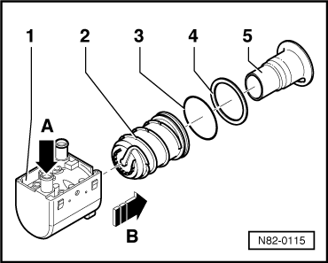
| Use a suitable screwdriver to carefully press the heat exchanger -2- through the rear water connection (water inlet) -arrow A- out of the water jacket -1- in the direction of -arrow B-. |

Note | This illustration shows a burner element -5- with round connection area. The burner element -5- fitted with this auxiliary heater has a connection area of rectangular design → Electronic parts catalogue. |
| Install in reverse order; paying attention to the following: |
| –
| If applicable, clean the inside and outside of the heat exchanger -2- with a brass wire brush (spark plug brush). |
| –
| Check the sealing surfaces at the heat exchanger -2- for damage. |
| –
| Prior to assembly, always replace the O-ring -3- and the seal -4-. |
|
|
|