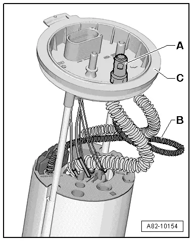
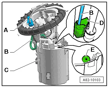
| The fuel for the auxiliary heater is drawn in via the connection -A- and the riser -B- from a steady zone -D- in the reservoir housing of the fuel delivery unit -C-. |

Note | t
| The riser -B- is attached in the reservoir housing of the fuel delivery unit -C-. This ensures that the auxiliary heater can still be operated even if the fuel tank is more or less empty. |
| t
| To stop the fuel tank becoming completely drained in auxiliary heating mode, the auxiliary heater is no longer activated if the fuel gauge (control unit in dash panel insert -J285-) is in the “red zone”. |
| t
| If the auxiliary heater functions properly when the fuel tank is completely full and problems are encountered if the tank is only partially full (fault message “No flame formation” or “Repeated flame interruption”), this is an indication of incorrect routing of the suction pipe -B- or that the bottom valve -E- of the fuel delivery unit is leaking. |
| t
| In the event of a leak in the bottom valve -E- in the reservoir housing of the fuel delivery unit -C-, the fuel level drops if the fuel tank is more or less empty and no further fuel can flow into the steady zone -D-. The fuel in the steady zone -D- is soon used up and this results in failure of the auxiliary heater. |
| t
| After removing and installing fuel system components, the fuel pipe to the metering pump -V54- is to be filled with fuel → Chapter. The auxiliary heater is then to be switched on and operated at full load for at least 10 minutes to ensure complete bleeding of the fuel pipe. |
|
|
|