audi Workshop Repair Guides

Audi Workshop Service and Repair Manuals

Bleeding coolant circuit > < Removing auxiliary heater
Installing auxiliary heater
  Note
t  The Audi A5 Coupé and the Audi A4 as of Model Year 2009 are gradually being fitted with adapted auxiliary heaters (with a modified supplementary heater control unit -J364-). These were fitted on the Audi Q5 right from the start of production. Pay attention to the correct version and assignment of the auxiliary heater to the vehicle → Electronic parts catalogue and → Vehicle diagnostic, testing and information systemVAS 5051/, “Guided fault-finding function”.
t  This auxiliary heater is installed in various vehicle models. The part number changes each time this auxiliary heater is fitted in a new vehicle model (e.g. from 8K0 xxx xxx to 8R0 xxx xxx on introduction of the Audi Q5 and subsequently to 4xx xxx xxx etc.). Attention must therefore be paid to correct assignment. Care must however also be taken to ensure that an old auxiliary heater version is never installed in a vehicle previously fitted with a newer version. For example, an Audi A4 provided at the factory with an auxiliary heater with part number 8R0 xxx xxx is not to be fitted with an auxiliary heater with part number 8K0 xxx xxx → Electronic parts catalogue.
t  As of 10.2010 auxiliary heaters with part number 4xx xxx  xxx are gradually to be introduced. Service installation of this version of the auxiliary heater is also possible in vehicles originally fitted with an auxiliary heater with part number 8R0 xxx xxx or 8K0 xxx xxx. As however there are differences between certain components of the various auxiliary heater versions (e.g. the 2-pin connector for the power supply to the auxiliary heater control unit -J364-), attention must be paid to correct assignment when replacing individual components of the auxiliary heater → Electronic parts catalogue.
t  If an auxiliary heater with part number 4xx xxx  xxx is fitted, attention must also be paid with this version to correct encoding for the vehicle concerned (different functions are stored in the control unit depending on the type of vehicle encoded) → Electronic parts catalogue and → Vehicle diagnostic, testing and information systemVAS 5051/, “Guided fault-finding function”.
t  The holders for the auxiliary heater were gradually modified on the Audi Q5 in Model Year 2009. Pay attention to the correct assignment when replacing the auxiliary heater and holders → Electronic parts catalogue and → Anchor.
t  As of Model Year 2010 a start/stop system will be available as an optional extra for this vehicle in conjunction with certain engines. On these vehicles, pay attention to the correct version of the air conditioner operating and display unit, Climatronic control unit -J255- and of the auxiliary heater → Electronic parts catalogue and → "Guided fault-finding" function of vehicle diagnostic, testing and information system VAS 5051.
t  Vehicles with a start/stop system are not to be fitted with auxiliary heaters with part number 8K0 xxx xxx → Electronic parts catalogue and → "Guided fault-finding" function of vehicle diagnostic, testing and information system VAS 5051.
t  If, following replacement of the auxiliary heater or the supplementary heater control unit -J364-, the fault “Incorrect control unit fitted” is displayed, check that -J364- has been encoded for the correct type of fuel “Diesel” or “Petrol” and correct if necessary → "Guided fault-finding" function of vehicle diagnostic, testing and information system VAS 5051.
Install in the reverse order of removal → Chapter, paying attention to the following.
–  Insert the heater and hand-tighten the bolts and nuts.
   
–  Finish-tighten the bolts and nuts in the following sequence:
1 - Bolt -3- (2x on Audi Q5)
2 - Nut -1- (not fitted on Audi Q5)
3 - Nuts -2-
  Note
  A82-10116
t  The Audi Q5 is fitted with a different holder (two-part holder), which is attached to the longitudinal member by means of two bolts -3- and two nuts -2-.
t  Butt-joint the coolant hoses and secure with clamps at the marked locations.
t  Butt-joint the fuel pipes and secure with clips at the marked locations.
t  If applicable, replace the clamps with screw-type clamps or clips of the same type and secure these using suitable pliers → Electronic parts catalogue.
t  If the coolant circuit has been drained, a new circulation pump -V55- is not to be started up until the coolant circuit has been filled, as dry running could destroy the new pump.
t  Depending on the version of the auxiliary heater and the vehicle equipment, the exhaust pipe fitted between the auxiliary heater and the exhaust silencer of the auxiliary heater may be provided with thermal insulation (to protect the surrounding components) → Electronic parts catalogue.
–  Fill the coolant expansion tank with coolant as far as the upper mark → Engine, mechanics; Rep. Gr.19.
  A82-10155
–  Attach the coolant hose -4- to the circulation pump -V55- of the auxiliary heater and secure with the clamp.
–  Carefully unfasten the hose clamps up to Ø 25 mm -3094--2- and allow coolant to flow into the auxiliary heater.
–  As soon as coolant emerges from the upper connection of the auxiliary heater, attach the coolant hose -3- to the auxiliary heater and secure it with the clamp.
–  Detach both hose clamps up to Ø 25 mm -3094-.
–  Bleed the auxiliary heater coolant circuit → Chapter.
–  Fill the coolant expansion tank with coolant as far as the upper mark → Engine, mechanics; Rep. Gr.19.
  Note
t  Following installation, check the exhaust pipe, coolant hoses, fuel pipe and wiring to the auxiliary heater (must not make contact with other components).
  A82-10115
t  
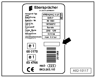
If the auxiliary heater has been replaced, the year of initial commissioning for the newly installed heater is to be entered on the heater rating plate -arrow- and on the new “duplicate rating plate” (the illustration shows a rating plate for an auxiliary heater in a vehicle with petrol engine).
t  There are different versions of the factory name plate.
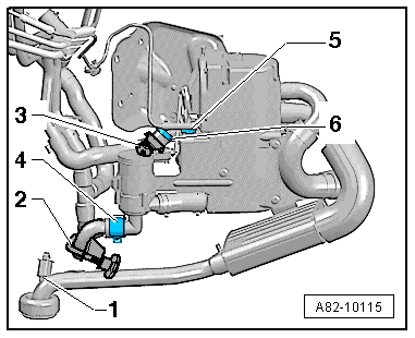
–  Check the position of the air intake and the intake air noise insulation of the auxiliary heater (air inlet and exhaust outlet must not be obstructed).
–  If necessary, release the component protection function for a newly installed auxiliary heater to cancel the interlocking of the auxiliary heater by the component protection → Vehicle diagnostic, testing and information systemVAS 5051/, “Guided fault-finding function”.
–  Check the encoding of the supplementary heater control unit -J364- → Vehicle diagnostic, testing and information systemVAS 5051/, “Guided fault-finding function”.
–  Interrogate the event recorder of the auxiliary heater control unit -J364- and erase any faults displayed → Vehicle diagnostic, testing and information systemVAS 5051/, “Guided fault-finding function”.
–  Check operation of the auxiliary heater remote control and perform adaption of the supplementary heater control unit -J364- if necessary → Vehicle diagnostic, testing and information systemVAS 5051/, “Guided fault-finding function”.
  Note
If the auxiliary heater is replaced together with the supplementary heater control unit -J364-, check the operation of at least one hand transmitter and re-adapt all hand transmitters if necessary (remote control hand transmitter adaption) → Vehicle diagnostic, testing and information system5051/, “Guided fault-finding function”.
–  Interrogate the adaption of the supplementary heater control unit -J364- and if necessary alter the adaption in the “Pipe filling” adaption channel (if a value other than “0” is displayed) and perform basic setting in the “Pipe filling” display group (to erase the “Pipe filling” fault) → Vehicle diagnostic, testing and information systemVAS 5051/, “Guided fault-finding function”.
  Note
t  If the value displayed in the “Pipe filling” adaption channel was other than “0”, perform the “Basic setting” function, “Pipe filling” display group (the metering pump -V54- is actuated for the time set in the “Pipe filling” adaption channel, the adaption in the adaption channel is reset to “0” and the fault “Pipe filling” is erased).
t  To stop an excessive amount of fuel being conveyed into the auxiliary/supplementary heater if the fuel pipe is already full, the value entered for the basic setting “Pipe filling” function must not be greater than “3” in the “Pipe filling” adaption channel → Vehicle diagnostic, testing and information systemVAS 5051/, “Guided fault-finding function”.
–  Start the engine and interrogate the event recorder of all the control units fitted. Faults may also have been entered for other control units by way of the data bus → Vehicle diagnostic, testing and information systemVAS 5051/, “Guided fault-finding function”.
–  After replacing auxiliary heater components, switch on the auxiliary heater and allow it to run for some time (at least 10 minutes) in full load mode before handing over the vehicle to the customer. There may still be remnants of factory lubricant for example in the components and these would evaporate following initial activation as soon as the components become hot.
Tightening torques → Chapter
  A82-10117

Bleeding coolant circuit > < Removing auxiliary heater