| t
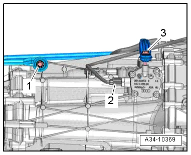
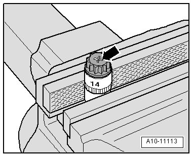
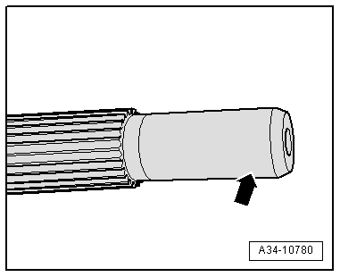
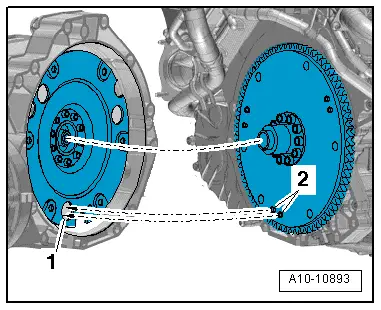
| Audi A4 vehicles from vehicle identification no. 8K-9-066500 onwards, Audi A5 vehicles from vehicle identification no. 8T-9-008000 onwards: aluminium bolts -2 ... 11- can be used twice only. After they have been used once, an „X“-arrow- must therefore be chiselled onto the bolts. |
| t
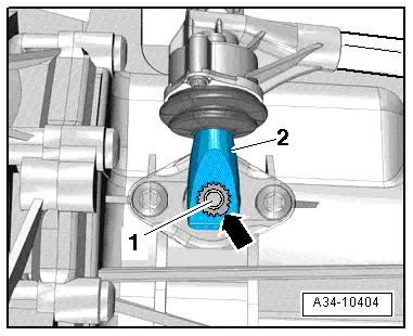
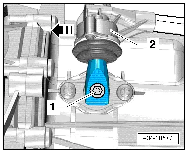
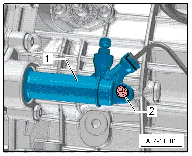
| To prevent damage to the bolts, they must not be clamped in a vice when marking them. Clamp a 14 mm socket with 1/2" drive in the vice instead, and insert the bolt into the socket, as shown in illustration. |
| t
| Bolts marked with an „X“ must not be used again. |
| t
| Audi A4 vehicles up to vehicle identification number 8K-9-066499: always renew aluminium bolts. |
| t
| Audi A5 vehicles up to vehicle identification number 8T-9-007999: always renew aluminium bolts. |
|
|
|

 Note
Note
 Caution