A4 Mk3
|
|
|
|
|
 Note
Note
|
|
|
|
 Caution
|
|
|
|
Note
|
|
|
|
|
|
|
|
Note
Note |
|
|
|
Note
|
|
Note
|
|
Note
|
|
|
|
|
|
Note
|
|
Note
|
|
Note
|
|
Note
|
|
| Component | Nm | ||
| Bolts and nuts | M6 | 9 | |
| M7 | 15 | ||
| M8 | 20 | ||
| M10 | 40 | ||
| M12 | 65 | ||
|
|
|
|
| Item | Bolt | Nm | ||||||||||
| 1 1) | M10x50 2) | 65 | ||||||||||
| 2 3), 7 | M12x100 4) | 30 + 90° | ||||||||||
| 3 5), 6 | M12x75 4) | 30 + 90° | ||||||||||
| 4, 5 5) | M12x120 4) | 30 + 90° | ||||||||||
| 8, 9 | M10x75 4) | 15 + 90° | ||||||||||
| 10 | M12x50 4) | 30 + 90° | ||||||||||
| A | Dowel sleeves for centralising | |||||||||||
| ||||||||||||
|
|
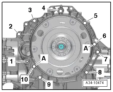
| Item | Bolt | Nm | ||||||
| 1 1) | M10x50 2) | 65 | ||||||
| 2 1), 4 … 6 | M12x100 3) | 30 + 90° | ||||||
| 7 | M12x125 3) | 30 + 90° | ||||||
| 8 | M10x60 3) | 15 + 90° | ||||||
| 9, 10 | M10x95 3) | 15 + 90° | ||||||
| A | Dowel sleeves for centralising | |||||||
| ||||||||
|
|
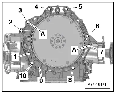
| Item | Bolt | Nm | ||||||
| 1 1) | M10x50 2) | 65 | ||||||
| 2 1), 3, 4, 5, 6 | M12x100 3) | 30 +90° | ||||||
| 7 | M12x175 3) | 30 +90° | ||||||
| 8, 9, 10 | M10x60 3) | 15 +90° | ||||||
| A | Dowel sleeves for centralising | |||||||
| ||||||||
|
|
| Item | Bolt | Nm | ||||||
| 1 1) | M10x50 2) | 65 | ||||||
| 2 1), 4 … 6 | M12x100 3) | 30 + 90° | ||||||
| 7 | M12x125 3) | 30 + 90° | ||||||
| 8 | M10x60 3) | 15 + 90° | ||||||
| 9, 10 | M10x95 3) | 15 + 90° | ||||||
| A | Dowel sleeves for centralising | |||||||
| ||||||||