audi Workshop Repair Guides

Audi Workshop Service and Repair Manuals

Exploded view - selector lever handle, selector lever position display Y26 > < Removing and installing gear selector position P switch F305
Removing and installing shift unit
Special tools and workshop equipment required
   
t  Removal lever -80 - 200-
  W00-0353
t  Counterhold tool -T10172- with -T10172/5-
  W00-10637
Removing
–  Remove front silencer or front exhaust pipe → Rep. Gr.26.
–  Remove bolts -arrows- and detach heat shield -1- for propshaft.
  A10-10859
–  Remove securing bolts from connection between propshaft and gearbox (counterhold using counterhold tool -T10172- with -T10172/5-).
–  Slide propshaft together towards rear final drive. The constant velocity joints can be moved axially.
–  Leave propshaft suspended.
  A39-10185
–  Release fasteners -arrows- and remove heat shield -1-.
  A37-10862
–  Use removal lever -80 - 200- to pry ball socket -1- on selector lever cable off selector shaft lever.
–  Pry off retaining clip -2- and detach selector lever cable from gearbox.
  Note
Do not bend or kink the selector lever cable.
  A37-10860
–  Remove multimedia operating unit -E380- → Rep. Gr.91.
–  Remove front ashtray → Rep. Gr.68.
  A68-10296
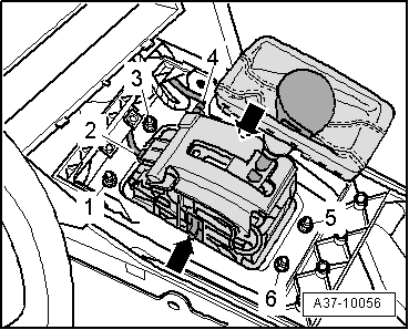
–  Unplug electrical connectors -2- and -4-.
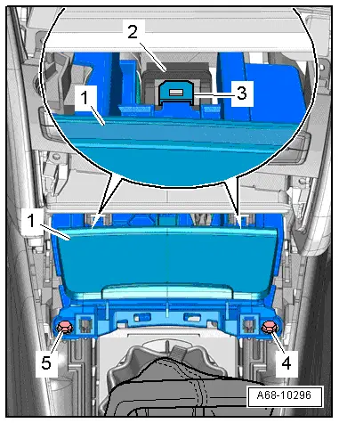
–  Remove insulating mat above selector mechanism.
  Note
t  Insulating mat is not shown in illustration.
t  The assistance of a second mechanic is required to detach the selector mechanism from below.
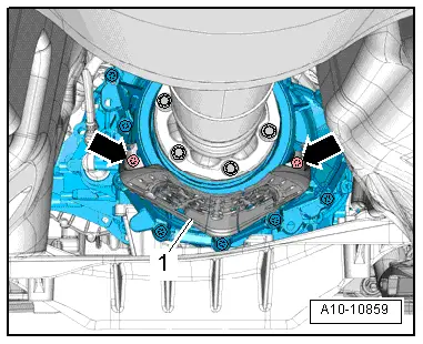
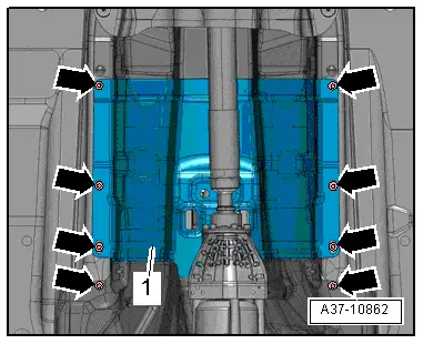
–  Remove bolts -1, 3, 5, 6-.
  Note
As the retaining clips -arrows- are no longer installed on some versions, the selector mechanism may drop as soon as the bolts are removed.
–  Detach selector mechanism from below.
Installing
Installation is carried out in reverse sequence; note the following:
l  Tightening torques → Chapter
  Note
t  
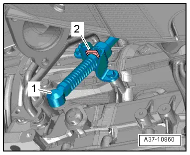
Before installing, lightly lubricate ball socket on selector lever cable with polycarbamide grease -G 052 142 A2-.
t  Do not bend or kink the selector lever cable.
–  Adjust selector lever cable → Chapter.
–  Check selector mechanism → Chapter.
–  Install propshaft → Rear final drive 0BC; Rep. Gr.39 or → Rear final drive 0BD; Rep. Gr.39.
–  Install front silencer or front exhaust pipe → Rep. Gr.26.
–  Install front ashtray → Rep. Gr.68.
–  Install multimedia operating unit -E380- → Rep. Gr.91.
  A37-10056

Exploded view - selector lever handle, selector lever position display Y26 > < Removing and installing gear selector position P switch F305