audi Workshop Repair Guides

Audi Workshop Service and Repair Manuals

Removing and installing selector lever sensors control unitJ587 and tiptronic switchF189 > < Manual release for selector mechanism
Removing and installing selector lever lock solenoidN110
Removing and installing selector lever lock solenoid -N110-
   
Removing
–  Shift selector lever into position „P“.
–  Remove multimedia system operating unit -E380- → Communication; Rep. gr.91.
–  Remove front ashtray → General body repairs, interior; Rep. gr.68.
  A68-10296
–  Unscrew nuts -1, 3, 5, 6- a few turns, but do not remove completely.
  Note
This will lower the shift unit slightly and facilitate removal.
  A37-10056
  Caution
The selector mechanism can be damaged by broken retaining clips, retaining tabs or other objects.
Make sure that no parts or objects drop into the selector mechanism. If this happens, the selector mechanism will have to be renewed!
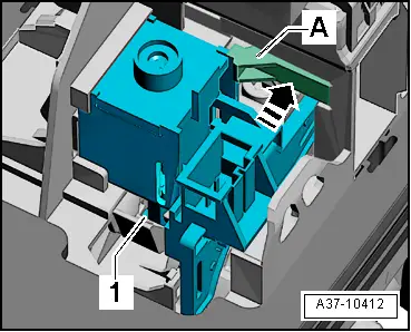
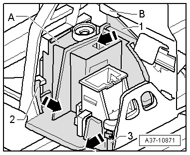
–  Release retaining tabs -2- and -3- in direction of -arrow-, lift front of sealing cap -A- slightly and hold in that position.
  Note
This prevents the retaining tabs from engaging again.
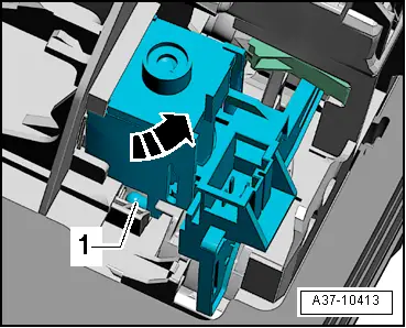
–  Using a screwdriver, release top retaining tab -1- of sealing cap from retainer -B- in direction of -arrow- and lift out sealing cap -A-.
  A37-10871
–  Unplug electrical connector on selector lever lock solenoid -N110-.
–  Press retaining hook -A- in direction of -arrow- and hold in this position.
  Note
The shift unit must be renewed if the retaining hook -A- breaks off.
  A37-10412
–  Tilt bottom part of selector lever lock solenoid -N110- out in direction of -arrow- so that ball head -1- disengages from operating lever on selector mechanism.
–  Detach selector lever lock solenoid -N110-.
Installing
Installation is carried out in reverse sequence; note the following:
l  Tightening torque → Chapter „Exploded view - selector mechanism“
–  Turn ball head -1- into correct position for installation.
–  Guide selector lever lock solenoid -N110- into selector mechanism at an angle from above and tilt bottom part in opposite direction of -arrow-.
  A37-10413
l  Ball head -1- must engage fully in operating lever on selector mechanism; press home with a small screwdriver if necessary.
–  Secure selector lever lock solenoid -N110- to retaining hook -A-.
  A37-10412
–  Place cover -A- over selector lever lock solenoid -N110- and carefully engage -1 ... 3-.
–  Attach electrical connectors.
–  Check function of selector mechanism before continuing assembly → Chapter.
–  Install front ashtray → General body repairs, interior; Rep. gr.68.
–  Install multimedia system operating unit -E380- → Communication; Rep. gr.91.
  A37-10871

Removing and installing selector lever sensors control unitJ587 and tiptronic switchF189 > < Manual release for selector mechanism