| –
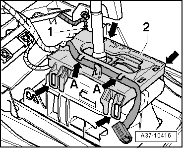
| Unplug electrical connector -1-. |
| –
| Release 4 retaining tabs -arrows- and lift out selector lever sensors control unit -J587- with tiptronic switch -F189-. |

Note | -Arrows A- can be disregarded. |
| Installation is carried out in reverse sequence; note the following: |
| –
| Make sure selector lever sensors control unit -J587- with tiptronic switch -F189- clicks in place with 4 retaining tabs -arrows-. |
| –
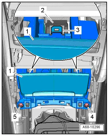
| Secure wiring for selector lever position display -Y26--arrows-. |
|
|
|