audi Workshop Repair Guides

Audi Workshop Service and Repair Manuals

Removing gearbox - vehicles with 3.2 ltr. FSI engine > < Removing gearbox - vehicles with 1.8 ltr. and 2.0 ltr. TFSI engine
Installing gearbox - vehicles with 1.8 ltr. and 2.0 ltr. TFSI engine
Special tools and workshop equipment required
   
t  Ring spanner insert, 16 mm -V.A.G 1332/14-
  W00-1329
t  Assembly aid -T40169-
  W00-10593
t  Transportation lock -T40170-
Procedure
  Note
t  Renew bolts which are tightened by turning through a specified angle.
t  Renew self-locking nuts and bolts, and seals, O-rings and gaskets.
t  Hose connections and hoses for charge air system must be free from oil and grease before fitting.
t  Secure all hose connections with the correct hose clips (as original equipment); refer to → Electronic parts catalogue.
t  To ensure that the charge air hoses can be connected securely, you must spray the screws on used screw-type clips with rust remover prior to installation.
t  Re-attach all cable ties at the same locations when re-installing.
Tightening torques for installing gearbox: → Anchor
–  Before fitting a replacement gearbox, always blow through the ATF cooler and ATF lines with compressed air (not more than 10 bar) → Chapter.
–  Before installing, it is important to clean any residue from threads in cylinder block using a tap.
  W00-10594
–  When fitting a replacement gearbox: attach gearbox support, gearbox mounting and tunnel cross member to new gearbox → Chapter.
–  Attach bracket -1- for exhaust system mounting to new gearbox → Engine, mechanics; Rep. gr.26.
  A34-10503
–  Position gearbox on gearbox support -T40173- and secure with tensioning strap -1-, as shown in illustration.
  A37-10849
–  The following preparations must be made before joining the engine and gearbox:
–  Insert assembly aid -T40169- into gearbox housing and dual-mass flywheel from below, as shown in illustration.
l  The assembly aid -T40169- must engage in the semi-circular recess -1- and in the inspection hole -2-.
  Note
There is only one inspection hole at the periphery; turn the dual-mass flywheel accordingly.
  A10-10825
–  Insert transportation lock -T40170- into gearbox housing from below and clamp onto flange shaft -1-.
  A10-10826
–  Check that dowel sleeves -A- for centralising engine/gearbox are in the cylinder block; install any missing dowel sleeves.
–  Check whether aluminium bolts for engine/gearbox connection can be reused and mark bolts if necessary → Anchor.
–  Join gearbox with engine and tighten bolts -2 … 6-.
  Note
  A37-10881
t  Bolt -2- also secures the starter to the gearbox and has an additional spacer sleeve -arrow-.
t  The spacer sleeve must be fitted between the starter and the gearbox.
–  Take out retainer -T40170- (transport lock) and assembly aid -T40169-.
  A34-10501
–  Disengage spindles -10 - 222 A /11-.
  A10-10993
–  Raise gearbox and tighten bolts -arrows- for tunnel cross member → Chapter.
–  Slacken tensioning strap and move engine and gearbox jack -V.A.G 1383 A- with gearbox support -T40173- out from underneath gearbox.
  Note
  A10-10866
The following step is necessary to ensure that the dual-mass flywheel makes even and proper contact on the drive plate and does not cant.
–  Slightly press dual-mass flywheel -2- against drive plate -3- in direction of -arrow- using a suitable lever -1-.
  A34-10497
–  Secure dual-mass flywheel to drive plate as follows:
–  Install first bolt -arrow- and tighten hand-tight (2 Nm).
  A10-10629
–  Turn crankshaft at vibration damper 240° in direction of engine rotation using counterhold tool -T10355-.
  A13-10442
–  Tighten bolt -arrow- accessible in this crankshaft position to 60 Nm.
–  Turn crankshaft 120° further each time and tighten remaining two bolts to 60 Nm.
  A10-10629
The remaining installation steps are carried out in reverse sequence; note the following:
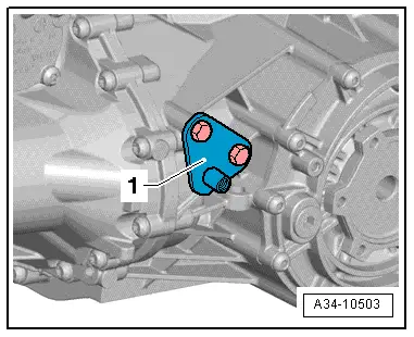
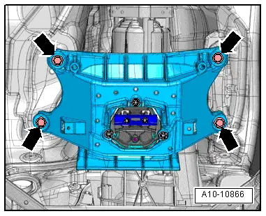
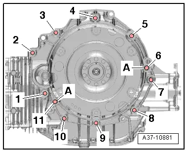
–  Tighten remaining engine/gearbox securing bolts -1, 7 … 11-.
–  Secure intermediate steering shaft to steering box → Running gear, front-wheel and four-wheel drive; Rep. gr.48.
–  Install selector lever cable → Chapter.
–  Install ATF lines → Chapter.
–  Secure drive shafts (left and right) to flange shafts on gearbox → Running gear, front-wheel drive and four-wheel drive; Rep. gr.40.
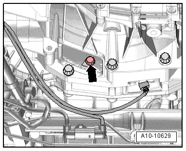
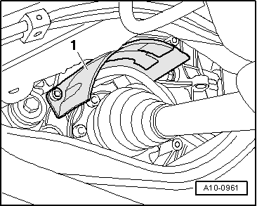
–  Install heat shield for drive shaft → Fig..
–  Install subframe cross brace → Running gear, front-wheel drive and four-wheel drive; Rep. gr.40.
–  Install diagonal struts → Running gear, front-wheel drive and four-wheel drive; Rep. gr.42.
–  Install noise insulation panels → General body repairs, exterior; Rep. gr.66.
–  Observe measures which have to be taken after connecting the battery → Electrical system; Rep. gr.27.
  Caution
Overvoltage can cause irreparable damage to control units.
Do not use charger for boost starting.
–  Check selector lever cable and adjust if necessary → Chapter.
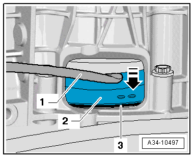
–  Check ATF level and top up as required → Chapter.
–  After performing repair work on gearbox, check gear oil level in front final drive and top up if necessary → Chapter.
Tightening torques
  Note
t  Tightening torques apply only to lightly greased, oiled, phosphated or black-finished nuts and bolts.
t  Additional lubricant such as engine or gear oil may be used, but do not use graphite lubricant.
t  Do not use parts which have been degreased.
t  Tolerance for tightening torques is ± 15 %.
  A37-10881
ComponentNm
Bolts and nutsM69
M715
M820
M1040
M1265
Dual-mass flywheel to drive plate60 1)
l  1) Renew bolts.

   
Heat shield for drive shaft - tightening torque
–  Tighten bolts for drive shaft heat shield (right-side) -1- to 23 Nm.
  A10-0961
Engine/gearbox securing bolts
  A37-10881
ItemBoltNm
1 1)M10x50 2)65
2 3), 7M12x100 4)5)30 + 90°
3, 6M12x75 4)5)30 + 90°
4, 5M12x120 4)5)30 + 90°
8, 9, 10M10x75 4)5)15 + 90°
11M12x50 4)5)30 + 90°
ADowel sleeves for centralising
l  1) Also secures starter.
l  2) Property class 10.9. The steel bolt can be re-used any number of times.
l  3) Also secures starter, with additional spacer sleeve between starter and gearbox.
l  4) Audi A4 vehicles up to vehicle identification no. 8K-9A-066499, Audi A5 vehicles up to vehicle identification no. 8T-9A-007999: renew aluminum bolts.
l  5) Audi A4 vehicles from vehicle identification no. 8K-9A-066500 onwards, Audi A5 vehicles from vehicle identification no. 8T-9A-008000: aluminium bolts can be used twice only → Anchor.

   
t  Audi A4 vehicles from vehicle identification no. 8K-9A-066500 onwards, Audi A5 vehicles from vehicle identification no. 8T-9A-008000 onwards: aluminium bolts -2 ... 11- can be used twice only. After they have been used once, an „X“-arrow- must therefore be chiselled onto the bolts.
t  To prevent damage to the bolts, they must not be clamped in a vice when marking them. Clamp a 14 mm socket with 1/2" drive in the vice instead, and insert the bolt into the socket, as shown in illustration.
t  Bolts marked with an „X“ must not be used again.
  A10-11113

Removing gearbox - vehicles with 3.2 ltr. FSI engine > < Removing gearbox - vehicles with 1.8 ltr. and 2.0 ltr. TFSI engine