audi Workshop Repair Guides

Audi Workshop Service and Repair Manuals

Installing gearbox - vehicles with 3.2 ltr. FSI engine > < Installing gearbox - vehicles with 1.8 ltr. and 2.0 ltr. TFSI engine
Removing gearbox - vehicles with 3.2 ltr. FSI engine
   
Removing gearbox - vehicles with 3.2 ltr. FSI engine
Special tools and workshop equipment required
t  Support bracket -10 - 222 A-
t  Removal lever -80 - 200-
t  Engine and gearbox jack -V.A.G 1383 A-
t  Stepladder -VAS 5085-
t  Adapter -T40058-
t  Engine support bracket, basic set -T40091-

   
t  Engine bung set -VAS 6122-
  W00-10435
t  Engine support bracket, supplementary set -T40093-
  W00-10354
t  Gearbox support -T40173-
Procedure
–  Bring wheels into straight-ahead position.
  W00-10596
  Caution
When disconnecting the battery there is a risk of serious damage to electronic components:
Observe the correct procedure for disconnecting the battery.
–  Disconnect earth wire -2- from battery terminal → Electrical system; Rep. gr.27.
  A27-10141
–  Remove engine cover panel (rear) -top arrows-.
  A10-10940
–  Remove cover -1- for drive shaft from wheel housing (both sides).
  A10-10179
–  Remove noise insulation panels → General body repairs, exterior; Rep. gr.66.
–  Remove front silencers (left and right) → Engine, mechanics; Rep. gr.26.
  A10-10823
–  Remove bolt -arrow- for ATF lines.
–  Remove plenum chamber partition panel → General body repairs, exterior; Rep. gr.50.
  Note
  A37-10839
Place a cloth below the connection to catch escaping ATF.
–  Remove bolts -1- and -2-, detach ATF lines from gearbox and tie up ATF lines.
–  Seal off open lines and connections with clean plugs from engine bung set -VAS 6122-.
  A37-10866
–  Remove nuts -arrows- and bolt -1- and press catalytic converter (right-side) to right side of vehicle.
  Note
For illustration purposes, the installation position is shown with the engine removed.
  A26-10352
–  Remove bolts -2 … 5- securing gearbox to engine (accessible from above).
–  Secure catalytic converter (right-side) loosely to exhaust manifold again with a nut to prevent it from dropping.
  A34-10370
–  Set up support bracket -10 - 222 A- with connecting piece -T40091/3- on suspension turrets (left and right), as shown in illustration.
–  Hook spindle -10 - 222 A /11- onto engine lifting eye (right-side).
  A34-10407
–  Attach remaining parts of support bracket -10 - 222 A- as shown in illustration. Set up support -T40093/3- on metal flange of longitudinal member.
–  Hook spindle -10 - 222 A /11- onto engine lifting eye (front left) and take up weight of engine.
  A34-10408
–  Remove bolts -arrows- and detach heat shield for drive shaft (right-side).
  A37-10841
–  Remove bolts -arrows- and detach heat shield for drive shaft (left-side).
–  Unbolt drive shafts (left and right) from flange shafts on gearbox.
  A34-10397
–  Detach intermediate steering shaft from steering box and telescope shaft upwards → Running gear, front-wheel drive and four-wheel drive; Rep. gr.48.
  Caution
Risk of damage to parts of the running gear.
Do not let the vehicle down on the wheels if the gearbox mounting, steering box or subframe cross brace are not properly installed.
  A48-10191
A4 (all models), A5 Coupé, A5 Sportback:
–  Remove subframe cross brace → Rep. gr.40.
  A40-10133
A5 Cabriolet:
–  Remove bolts -1- and -2- (left and right) and detach diagonal strut.
  A40-10125
–  Remove subframe cross brace → Rep. gr.40.
  A40-10134
Continued for all vehicles:
–  Unplug electrical connector -2- for engine speed sender -G28- and move wiring clear.
  Note
-Item 1- can be disregarded.
  A10-10869
–  Remove bolt -1-, press retainer off gearbox and swivel back towards rear -arrow-.
  A34-10398
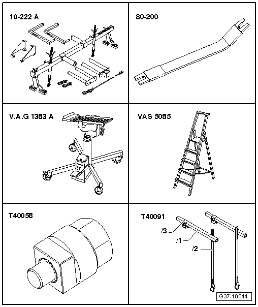
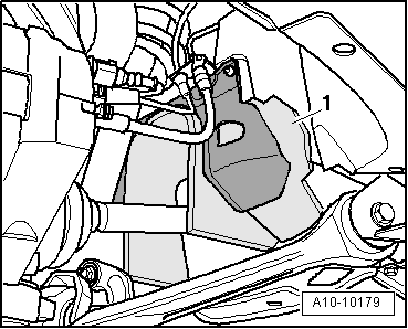
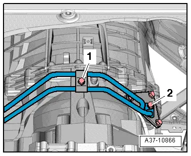
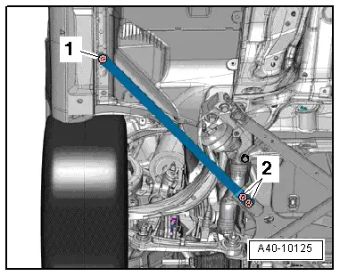
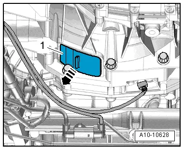
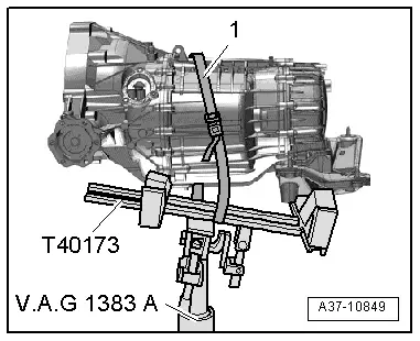
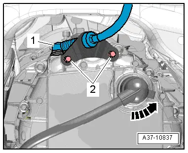
–  Use removal lever -80 - 200- to press ball socket -1- on selector lever cable off gearbox selector lever.
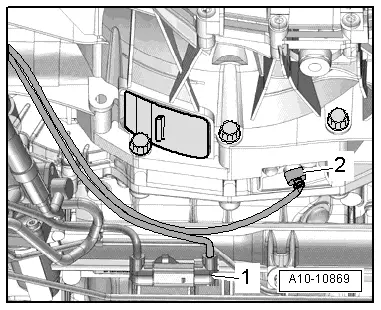
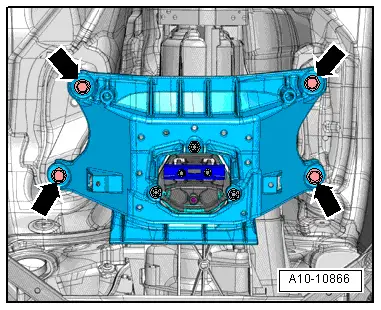
–  Remove bolts -2- for cable support bracket.
–  Move selector lever cable clear.
  Note
Do not bend or kink the selector lever cable.
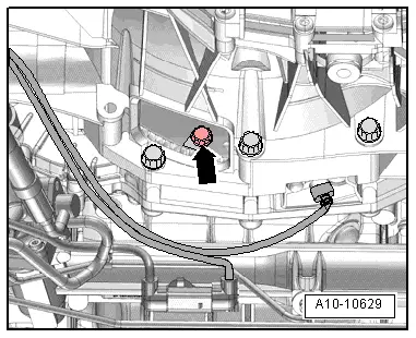
  Caution
The gearbox control unit (mechatronic unit) can be damaged by electrostatic discharge.
t  Before handling the electrical connector, the mechanic must discharge static by briefly touching an earthed metal object, such as vehicle earth, lifting platform or heater radiator, etc.
t  Do not touch contact pins in gearbox connector with bare hands.
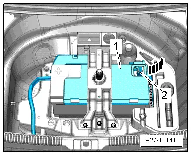
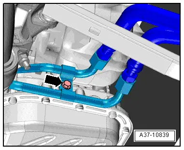
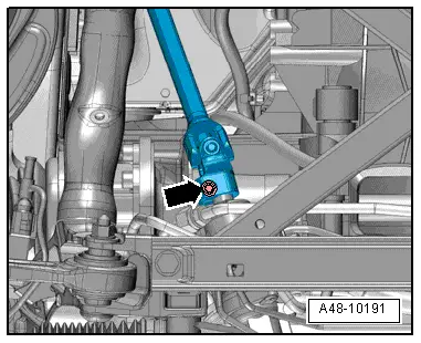
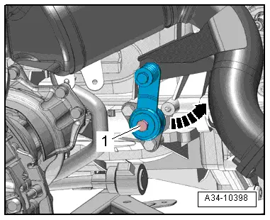
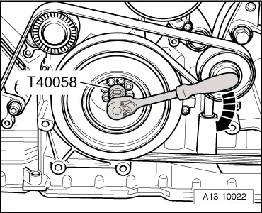
–  Turn fastener anti-clockwise -arrow- and unplug electrical connector on gearbox.
  A37-10837
–  Pull cover -1- off bottom of gearbox -arrow-.
  A10-10628
–  Insert guide stud of adapter -T40058- as follows:
l  The larger diameter -arrow 1- faces engine.
l  The smaller diameter -arrow 2- faces adapter.
  A13-10026
–  To slacken bolts for drive plate, counterhold crankshaft with adapter -T40058- at vibration damper.
  Note
When you then turn the crankshaft, only turn crankshaft in direction of engine rotation -arrow-.
  A13-10022
–  Remove 6 bolts -arrow- for drive plate (turn crankshaft 60° in direction of engine rotation each time).
  A10-10629
–  Remove bolt -1- for starter.
–  Detach starter from gearbox but do not remove starter.
–  Remove remaining engine/gearbox securing bolts -6 … 11-.
  A34-10370
–  Position engine and gearbox jack -V.A.G 1383 A- with gearbox support -T40173- underneath gearbox and secure with tensioning strap -1- as shown in illustration.
  Note
  A37-10849
For illustration purposes, the gearbox support -T40173- is not shown.
–  Remove bolts -arrows- for tunnel cross member.
  A10-10866
–  Apply light tension to both spindles -10 - 222 A /11-.
  A34-10408
–  Detach gearbox from engine and lower carefully using engine and gearbox jack -V.A.G 1383 A-.
  A37-10849

Installing gearbox - vehicles with 3.2 ltr. FSI engine > < Installing gearbox - vehicles with 1.8 ltr. and 2.0 ltr. TFSI engine