audi Workshop Repair Guides

Audi Workshop Service and Repair Manuals

Renewing oil seals for flange shafts (rear final drive removed) > < Removing and installing rear final drive - Audi A8
Removing and installing rear final drive - Audi Q5 hybrid
Special tools and workshop equipment required
   
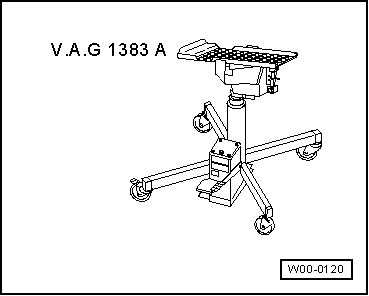
t  Engine and gearbox jack -V.A.G 1383 A- with universal gearbox support -V.A.G 1359/2-
  W00-0120
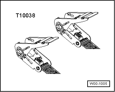
t  Tensioning strap -T10038-
  W00-1005
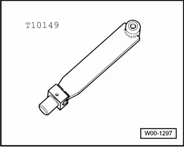
t  Support -T10149-
  W00-1297
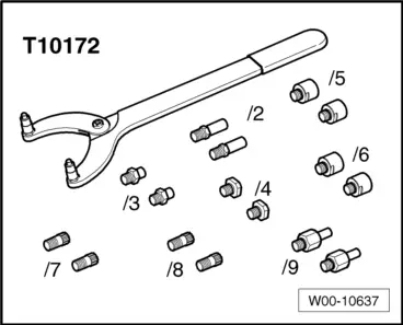
t  Counterhold tool -T10172- with adapters -T10172/5-
  W00-10637
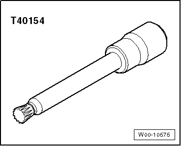
t  Socket -T40154-
Removing rear final drive
Observe safety precautions → Chapter.
Refer to general repair instructions → Chapter.
–  Place vehicle on lifting platform.
De-energising high-voltage system
  WARNING
Observe general warning instructions for work on the high-voltage system → Electrical system; Rep. gr.93.
The high-voltage system must be de-energised according to the Guided Fault Finding routine in the ⇒ vehicle diagnostic tester, and ONLY by this method.
  DANGER!
High voltage can cause fatal injury.
Danger of severe or fatal injuries from electric shock.
t  Voltage levels in the high-voltage system constitute a safety hazard.
t  For reasons of safety, persons with life-preserving or other electronic medical devices in or on their body must not perform any work on the high-voltage system. Such medical devices include internal analgesic pumps, implanted defibrillators, pacemakers, insulin pumps and hearing aids.
t  The high-voltage system may only be de-energised by a suitably qualified person (Audi high-voltage technician).
t  It must be definitely confirmed that the high-voltage system is de-energised. The system may only be de-energised using the vehicle diagnostic tester via „Guided Fault Finding“.
t  The qualified person (Audi high-voltage technician) confirms that the system is de-energised and ensures that it cannot be re-energised by storing the ignition key and the maintenance connector for high-voltage system - TW - in a safe place.
t  The qualified person (Audi high-voltage technician) marks the vehicle by attaching the appropriate warning signs.
  Note
t  De-energising high-voltage system:
t  Connect vehicle diagnostic tester.
t  Select Guided Fault Finding mode.
t  Using the GoTo button, select the following menu options in succession.
t  Function/Component Selection
t  Body
t  Electrical system
t  Self-diagnosis-compatible systems
t  8C - Hybrid battery management -J840
t  8C - Hybrid battery management, functions
t 
t  51 - De-energise high-voltage system (Rep. Gr. 93)
–  Detach wheel trim from rear left wheel (on vehicles with light alloy wheels, pull off trim cap using puller from vehicle tool kit).
–  Remove rear left wheel.
  W00-10575
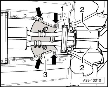
–  Remove rear section of exhaust system -2- → Rep. gr.26.
  Note
A second mechanic is required for removing the rear section of the exhaust system.
–  Detach heat shield -3- from body -arrows-.
  A39-10010
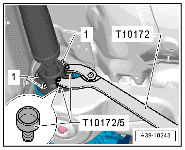
–  Detach propshaft from rear final drive → Chapter.
  A39-10243
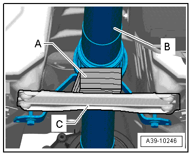
–  Place a block of wood -A- (approx. 40 mm high) on rear cross member -C- to support propshaft -B-.
  Note
t  On the Audi Q5, the propshaft -B- is supported by the heat shield below the centre bearing.
t  The propshaft can be bent as far as the stop at the centre joint, but must not be subjected to any kind of force. The centre joint or the protective boot can be damaged if the joint is forced against its stop.
  A39-10246
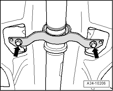
–  Remove bolts -arrows- securing centre propshaft bearing.
–  Push propshaft forwards and at the same time pull it off rear final drive.
–  Tie propshaft up to one side on subframe.
  A34-10206
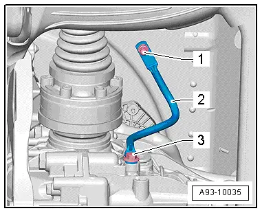
–  Remove bolt -3- for potential equalisation line -2-.
  A93-10035
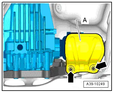
–  Detach heat shield -A- for drive shaft (left-side) from cross member/rear final drive -arrows-.
  A39-10249
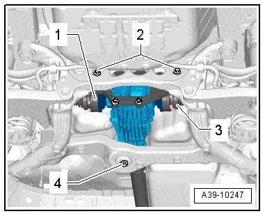
–  Unbolt drive shafts on both sides -1- and -3-.
–  Slacken off bolts -2- approx. 3 turns.
–  Remove bolt -4-.
  A39-10247
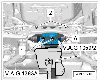
–  Place engine and gearbox jack -V.A.G 1383 A- with universal gearbox support -V.A.G 1359/2- and a suitable block of wood -A- (approx. 80 mm high) below rear final drive.
  Note
Make sure that universal gearbox support -V.A.G 1359/2- does not make contact with fuel tank.
–  Remove bolts -1- (bottom bolts securing cross member to rear final drive) and -2-.
  A39-10248
–  Remove 2 top bolts securing cross member -B- to rear final drive.
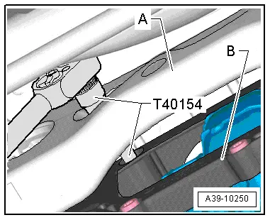
–  For this step, guide socket -T40154- through holes in subframe -A-. If necessary, move final drive slightly to either side.
  A39-10250
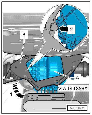
–  Then push final drive -A- slightly forwards.
–  Turn cross member -B- towards the bottom left -arrow 1-, guide past final drive -arrow 2- and remove.
  Note
t  A 2nd mechanic is required for the next steps when removing the rear final drive.
t  Before lifting the rear left suspension, the vehicle must be secured to the lifting arm of the lifting platform with tensioning strap -T10038-.
–  Take out engine and gearbox jack -V.A.G 1383 A- from below rear final drive; 2nd mechanic must hold final drive to prevent it from dropping.
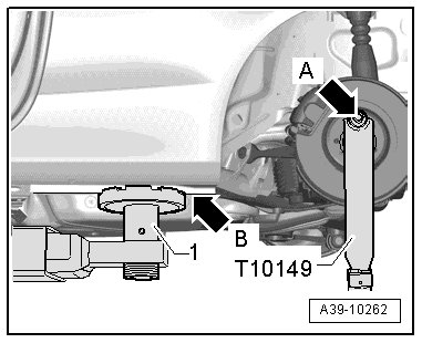
–  Attach support -T10149- to engine and gearbox jack -V.A.G 1383 A-.
  A39-10251
–  Attach support -T10149- to rear left wheel hub using wheel bolt -arrow A-.
–  Using engine and gearbox jack -V.A.G 1383 A-, lift rear left suspension until vehicle starts to come clear of lifting arm -1- of lifting platform -arrow B-. Do not lift vehicle further.
  WARNING
t  Do not raise or lower vehicle while engine and gearbox jack -V.A.G 1383 A- is positioned under the vehicle.
t  Do not leave engine and gearbox jack -V.A.G 1383 A- under vehicle for longer than necessary.
  A39-10262
–  2nd mechanic must now push rear final drive -1- towards left side of vehicle in direction of -arrow-.
–  Guide drive shaft (right-side) -5- upwards out of flange shaft -4- of rear final drive.
–  Then disengage drive shaft (left-side) -3- and, with assistance of 2nd mechanic, detach final drive rearwards from subframe -2-.
Installing rear final drive
Perform installation in reverse sequence of removal. Note the following:
  WARNING
Working on vehicles with high-voltage wiring:
l  Do not support yourself or tools on high-voltage wiring or associated components --> this can damage the insulation.
l  High-voltage wiring must not be excessively bent or kinked --> this can damage the insulation.
l  The round high-voltage connectors are colour-coded with an external coloured ring and are provided with mechanical coding or guide lugs. It is important to observe this coding when joining up the round high-voltage connectors, otherwise the connectors can be damaged.
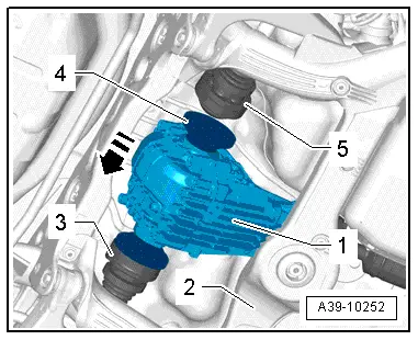
  A39-10252
–  With assistance of 2nd mechanic, bring rear final drive -1- into installation position on subframe -2-.
–  Fit drive shaft (left-side) -arrow 3- into flange shaft of final drive.
–  2nd mechanic must now push rear final drive -1- towards left side of vehicle in direction of -arrow-.
–  Then fit drive shaft (right-side) -5- into flange shaft -4- of final drive.
–  Detach engine and gearbox jack -V.A.G 1383 A- with support -T10149- from rear left suspension.
  A39-10252
–  Place engine and gearbox jack -V.A.G 1383 A- with universal gearbox support -V.A.G 1359/2- and a suitable block of wood (approx. 80 mm high) below rear final drive -A-.
–  Then push final drive -A- slightly forwards.
–  Turn cross member -B- towards top left in opposite direction to -arrow 1- and bring into position, guiding past final drive -arrow 2-.
  A39-10251
–  Now tighten 4 bolts securing cross member -B- to rear final drive in diagonal sequence. Tightening torque → Item
–  For this step, guide socket -T40154- through holes in subframe -A-. If necessary, move final drive slightly to either side.
  A39-10250
–  Screw in bolts -2- and -4- and tighten hand-tight initially.
  Note
For illustration purposes the final drive is shown without engine and gearbox jack -V.A.G 1383 A- and universal gearbox support -V.A.G 1359/2-.
–  Tighten bolt -4-. Tightening torque → Item
–  Then tighten bolts -2-. Tightening torque → Item
–  Take out engine and gearbox jack -V.A.G 1383 A- from below final drive.
–  Secure drive shafts -1- (left-side) and -3- (right-side) → Running gear, front-wheel drive and four-wheel drive; Rep. gr.42.
  A39-10247
–  Bolt potential equalisation line -2- onto rear final drive.
l  Tightening torque for bolt -3- on final drive: 20 Nm
  A93-10035
–  Install heat shield -A- for drive shaft (left-side) on cross member/rear final drive -arrows- → Item.
  A39-10249
–  Bolt propshaft onto rear final drive → Anchor.
–  Secure centre propshaft bearing to body so it is free of stress. Tightening torque → Item
–  Check gear oil level in rear final drive → Chapter.
  A34-10206
–  Secure heat shield -3- to body -arrows-.
–  Install rear section of exhaust system and perform stress-free alignment → Rep. gr.26.
–  If fitted, install cross member -1- → Rep. gr.66.
–  Install rear left wheel and tighten wheel bolts → Wheels and tyres; Rep. gr.44.
Re-energising high-voltage system
The high-voltage system must be re-energised according to the Guided Fault Finding routine in the vehicle diagnostic tester, and ONLY by this method.
  DANGER!
High voltage can cause fatal injury.
Danger of severe or fatal injuries from electric shock.
t  Voltage levels in the high-voltage system constitute a safety hazard.
t  For reasons of safety, persons with life-preserving or other electronic medical devices in or on their body must not perform any work on the high-voltage system. Such medical devices include internal analgesic pumps, implanted defibrillators, pacemakers, insulin pumps and hearing aids.
t  The high-voltage system may only be re-energised by a suitably qualified person (Audi high-voltage technician).
t  The system may only be re-energised using the vehicle diagnostic tester via „Guided Fault Finding“.
t  The vehicle is then made ready for operation again by the qualified person (Audi high-voltage technician).
t  The qualified person (Audi high-voltage technician) marks the vehicle by attaching the appropriate warning signs.
  Note
t  Re-energising high-voltage system:
t  Connect vehicle diagnostic tester.
t  Select Guided Fault Finding mode.
t  Using the GoTo button, select the following menu options in succession.
t  Function/Component Selection
t  Body
t  Electrical system
t  Self-diagnosis-compatible systems
t  8C - Hybrid battery management -J840
t  8C - Hybrid battery management, functions
t  51 - Re-energise high-voltage system (Rep. Gr. 93)
  A39-10010

Renewing oil seals for flange shafts (rear final drive removed) > < Removing and installing rear final drive - Audi A8