
A4 Mk3
| Dismantling and assembling hydraulic control unit |

| 1 - | Bolt |
| q | 5 Nm |
| 2 - | Four-wheel drive pump -V415- |
| q | Removing and installing → Chapter |
| 3 - | O-ring |
| q | Always renew |
| 4 - | Adapter |
 Note
Note| t | Adapter can fall out during removal of four-wheel drive pump -V415- |
| t | Before installing four-wheel drive pump -V415-, insert adapter in recesses in hydraulic pump |
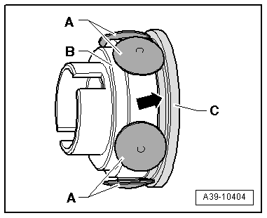
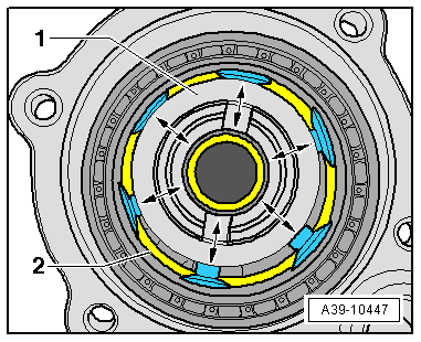
| 5 - | Hydraulic pump |
| q | Consists of guide ring, housing and 6 pistons |
| q | Assembling → Fig. |
| 6 - | Ball bearing |
| q | Can be removed and installed by hand |
| 7 - | Pipe (left-side) |
| q | Tighten nuts to 30 Nm |
| q | Installed between hydraulic control unit and superposition gear (left-side) |
| q | When installing, first screw in both nuts hand-tight |
| 8 - | O-ring |
| q | Always renew |
| 9 - | Oil pressure and oil temperature sender -G437- |
| q | 10 Nm |
| q | Brown connection |
| q | Removing and installing → Chapter |
| 10 - | Oil pressure and oil temperature sender 2 -G640- |
| q | 10 Nm |
| q | Black connection |
| q | Removing and installing → Chapter |
| 11 - | Clutch valve 2 for four-wheel drive -N446- |
| q | Colour: brown |
| q | Removing and installing → Chapter |
| q | Installation position: connector must face upwards towards oil pressure and oil temperature sender |
 Caution
|
| 12 - | Clutch valve for four-wheel drive -N445- |
| q | Colour: black |
| q | Removing and installing → Chapter |
| q | Installation position: connector must face upwards towards oil pressure and oil temperature sender |
Caution
|
| 13 - | Bolt |
| q | 2.5 Nm |
| 14 - | O-ring |
| q | Always renew |
| q | Fit on clutch valve |
| 15 - | Spring |
| q | Insert in guide → Item |
| 16 - | Guide |
| q | Installation position: large diameter must face ball → Item |
| 17 - | Ball |
| q | Before installing, insert in guide → Item |
| 18 - | Housing for hydraulic control unit |
| q | With centring pins -arrows- |
| q | Centring pins lock hydraulic control unit with gasket on final drive housing |
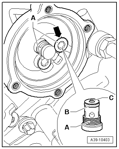
| 19 - | Ball |
| q | Before installing, insert in hole in shuttle valve → Item |
| 20 - | O-ring |
| q | Always renew |
| 21 - | Shuttle valve |
| q | 8 Nm |
| q | Removing and installing → Fig. |
| 22 - | Gasket |
| q | With strainer |
| q | Position on centring pins of housing for hydraulic control unit |
| 23 - | Pipe (right-side) |
| q | Tighten nuts to 30 Nm |
| q | Installed between hydraulic control unit and superposition gear (right-side) |
| q | When installing, first screw in both nuts hand-tight |
|
|
|
|
Note
|
|