audi Workshop Repair Guides

Audi Workshop Service and Repair Manuals

Servicing end cover > < Exploded view - removing and installing input shaft, output shaft, reverse gear wheel and selector plates / selector forks
Dismantling and assembling gearbox - assembly sequence
The end cover, side shaft, gearbox cover, input shaft and output shaft are removed and installed together with the internal gearbox selector mechanism.
  Note
t  The differential does not have to be removed in order to remove the above-mentioned components.
t  Refer to general repair instructions → Chapter.
   
Special tools and workshop equipment required
t  Drift sleeve -VW 244 B-
t  Thrust plate -40 -105-
t  Socket, multi-point bit -T10061-
t  Extractor tool -T20143-
t  Thrust piece -T40166-
t  Extractor -T40176-

   
t  Punch -3013-
t  Gearbox support -T40206-
t  Separating tool -T40213-
t  Support tool -T40214-
t  Guide pin -T40216-
t  Counterhold tool -T40217-

   
t  Thrust piece -3002-
  W00-0345
t  Engine and gearbox support -VAS 6095-
t  Locking fluid -AMV 185 101 A1-
t  Sealing paste -AMV 188 001 02-
t  Grease for clutch plate splines -G 000 100-
t  Lubricating paste -G 000 150-
t  Sealing grease -G 052 128 A1-
Dismantling gearbox
–  Lift gearbox with workshop hoist -VAS 6100- → Chapter.
  W00-1273
–  Place drip tray underneath.
–  Unscrew plug -arrow- and drain off gear oil.
  A34-10447
–  Secure gearbox to engine and gearbox support → Chapter.
–  Remove clutch module → Chapter.
–  Put clutch module down carefully, e.g. on work bench.
  A37-11038
–  Remove clutch release lever -1- together with release bearing -2- and retaining spring -3-.
–  Remove bolts -4- and detach retaining piece -5- (if fitted) with guide sleeve -6-.
  A34-10723
–  Prise out input shaft oil seal.
  A39-10265
–  Then remove circlip -arrow- in front of ball bearing for input shaft.
  Note
If this circlip cannot be removed, detach the gearbox cover first and knock the input shaft forwards using a rubber-headed hammer.
  A34-10592
–  Pierce through centre of sealing cap -A- for output shaft and prise out in direction of -arrow-.
  A34-10593
–  Remove bolts -A-, -B- and -arrows- securing end cover -C- to gearbox cover.
  Note
The centre hex studs -B- are not fitted on all versions, for allocation refer to → Electronic parts catalogue.
–  Detach end cover -C- from gearbox cover.
  A34-10784
Loosen twelve-point bolt -A- securing side shaft -B- to pinion shaft as follows:
–  Apply twelve-point socket -C- (21 mm) with extension -D- to twelve-point bolt -A-.
–  Engage external teeth -arrow 1- of counterhold tool -T40217- in internal splines -arrow 2- of side shaft -B-.
  A34-10596
–  Secure counterhold tool -T40217- to gearbox cover with M8 bolts -arrows-.
–  Loosen and unscrew twelve-point bolt securing side shaft to pinion.
-A- Torque wrench
  Note
t  Counterhold tool -T40217- remains in position on the gearbox cover.
t  When the counterhold tool -T40217- is attached, the output shaft is locked and will not turn.
  A34-10785
–  Now loosen bolt -A- on output shaft using socket -T10061-.
  Note
t  Bolt -A- has a very high release torque (approx. 300 - 350 Nm).
t  If necessary, heat bolt to approx. 80 °C using hot air blower -V.A.G 1416-. This will reduce the torque required to release the bolt. After dismantling the gearbox, check the seal of the ball bearing in the gearbox housing for damage. Renew ball bearing if necessary.
B - Torque wrench
–  Remove counterhold tool -T40217-.
  A34-10595
–  Pull side shaft -1- out of gearbox cover.
–  Detach circlip -2- and spur gear -3- (drive for side shaft) from output shaft -3-.
  Note
t  If the spur gear cannot be detached by hand, use two-arm puller e.g. -Kukko 20/10-. To do this, insert thrust piece -3002- in output shaft.
t  If necessary, detach oil collector → Item from gearbox cover.
  A34-10787
–  If fitted, remove gearbox neutral position sender -G701--A-.
–  To do this, remove bolt -arrow- and pull sender out of sealing cap -B- for selector shaft.
  Note
t  Sealing cap -B- remains fitted.
t  If a sealing plug is fitted in place of the gearbox neutral position sender -G701-, it does not have to be removed when dismantling and assembling the gearbox.
t  To prevent damage to oil seal for selector shaft in sealing cap -B-, screw guide pin -T40216- onto selector shaft → Anchor.
  A34-10786
–  Remove bolts -1- and carefully lever off selector shaft cover -2-.
  A34-10461
–  Lift selector shaft slightly -arrow A- and pull it out -arrow B-.
  A34-10462
–  Then turn gearbox in assembly stand or engine and gearbox support -VAS 6095- so that gearbox cover -C- faces upwards.
–  Remove bolts -A- securing bearing mounting and bolts -B- securing gearbox cover -C- to gearbox housing -D-.
  Note
For subsequent installation of the gearbox cover, note that the bolt marked with the -arrow- is a steel bolt, 50 mm long.
–  Take off gearbox cover -C-.
  A34-10599
–  Detach oil collector -1- from selector plate / selector fork for 3rd/4th gear -2- and from bearing mounting -3--arrows A…D-.
  A34-10600
–  Remove magnet -5- from gearbox housing and clean magnet.
  Note
-Items 1 ... 4- can be disregarded.
  A34-10788
–  Turn gearbox into a horizontal position on assembly stand or engine and gearbox support -VAS 6095-. Reverse gear wheel -1- with support for reverse shaft -2- then faces upwards.
  Note
-Arrow A- and -arrow B- can be disregarded.
  A34-10601
–  Attach separating tool -T40213- to gearbox support -T40206- with bolts -arrows-.
  Caution
Risk of damage to gears, shafts and bearings.
t  The input shaft and output shaft must be pressed out together.
t  It is permissible to turn the spindles alternately not more than one turn at a time when pressing out the shafts.
–  By turning spindles of separating tool -T40213- alternately one turn at a time, press input shaft and output shaft out of ball bearings in gearbox housing.
  A34-10725
–  At the same time, guide support for reverse shaft -2- out of retainer in gearbox housing -arrow B-.
–  Then detach reverse gear wheel -1- with support for reverse shaft -2- from input shaft.
  A34-10601
–  Detach input shaft -1- and output shaft -2- together with selector fork cluster -3- from gearbox housing.
–  If necessary, remove oil collector -4-.
Detach separating tool -T40213- from gearbox support -T40206-.
  A34-10788
Assembling gearbox
l  The reverse gear wheel with support for reverse shaft must be installed → Anchor before the input shaft -1- and output shaft -2- are seated in the ball bearings.
–  Install oil collector -4- and magnet -5- in gearbox housing.
–  Install input shaft -1- and output shaft -2- together with selector fork cluster -3- in gearbox housing.
  A34-10788
–  Install reverse gear wheel -1- with support for reverse shaft -2-. When doing this, fit lug -arrow A- into slot -arrow B- in gearbox housing.
  A34-10601
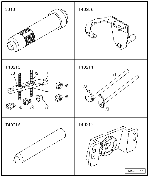
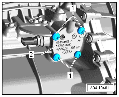
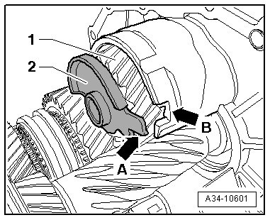
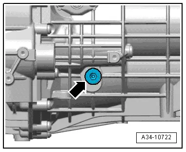
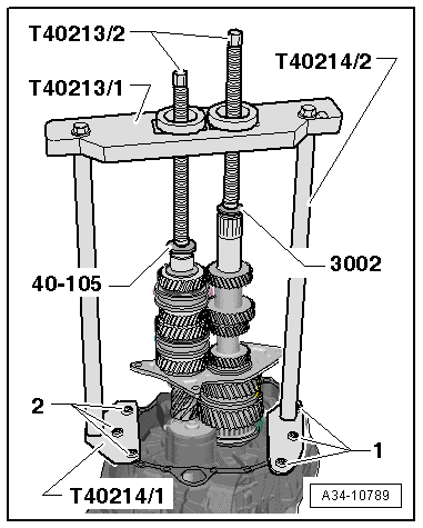
–  Secure supports -T40214/1- and -T40214/2- to gearbox housing, as shown in illustration, with bolts -1- and -2-.
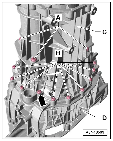
–  Attach plate -T40213/1- to supports -T40214/1- and -T40214/2-.
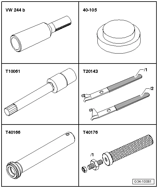
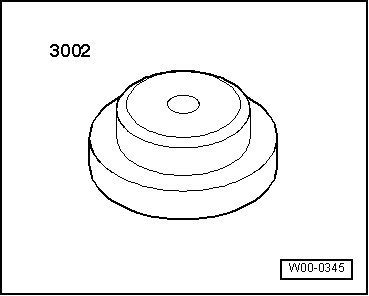
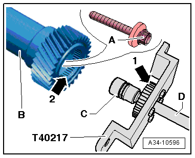
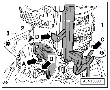
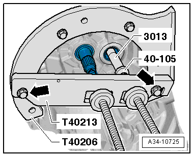
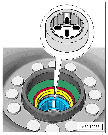
–  Fit thrust plate -40-105- on input shaft and thrust piece -3002- in aperture of output shaft.
  Caution
Risk of damage to gears, shafts and bearings.
t  
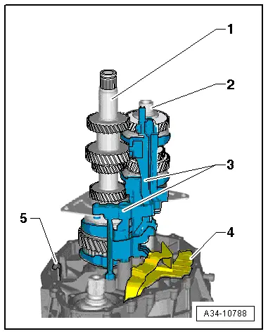
The input shaft and output shaft must be pressed in together.
t  It is permissible to turn the spindles alternately not more than one turn at a time when pressing in the shafts.
–  Then, by turning spindles -T40213/2- alternately one turn at a time, press in input shaft and output shaft until they are seated in ball bearings.
–  Detach separating tool -T40213- and supports -T40214-.
  A34-10789
–  Fit lug -arrow A- on oil collector -1- into hole -arrow B- in bearing mounting -3- and then clip oil collector onto bearing mounting -arrow C- and selector plate / selector fork for 3rd/4th gear -2--arrow D-.
–  Check that 2 dowel sleeves for centering gearbox cover and gearbox housing are fitted in gearbox housing.
–  Apply sealing paste -AMV 188 001 02- evenly and not too thickly onto contact surfaces between gearbox housing and gearbox cover.
  A34-10600
–  Fit gearbox cover -C- onto gearbox housing -D-.
–  Clean threads of bolts -A- with a wire brush. Then apply locking fluid -AMV 185 101 A1- and screw bolts hand-tight into bearing mounting.
–  Tighten new aluminium bolts -B- (16x; 35 mm long) to specified torque.
–  Tighten steel bolt -arrow- (50 mm long) below aperture for slave cylinder to specified torque.
–  Then tighten bolts -A- to specified torque.
  A34-10599
Determine thickness of circlip -arrow- for input shaft as follows:
–  Determine the thickest circlip that will just fit and install it. For part number refer to → Electronic parts catalogue.
  Note
Start with the thickest circlip.
The following circlips are available:
  A34-10592
Circlip thickness (mm)
3.443.473.50

   
Installation position of spur gear
l  Longer extension -arrow- for spur gear bearing faces towards gearbox cover.
l  Smaller diameter -a- of gear teeth faces end cover.
  A34-10790
–  Fit spur gear -A- on output shaft -B-.
  Note
If necessary, use press tool -40-21- to drive spur gear onto stop.
Determine thickness of circlip -C- for spur gear as follows:
–  Determine the thickest circlip that will just fit and install it. For part number refer to → Electronic parts catalogue.
The following circlips are available:
  A34-10791
Circlip thickness (mm)
2.232.352.47
2.262.382.50
2.292.41 
2.322.44 

   
–  Insert side shaft -B- all the way onto pinion shaft and into gearbox cover.
Tighten twelve-point bolt -A- securing side shaft -B- to pinion shaft as follows:
–  Apply twelve-point socket -C- (21 mm) with extension -D- to twelve-point bolt -A-.
–  Engage external teeth -arrow 1- of counterhold tool -T40217- in internal splines -arrow 2- of side shaft.
  A34-10596
–  Secure counterhold tool -T40217- to gearbox cover with M8 bolts -arrows-.
–  Tighten twelve-point bolt securing side shaft / pinion to specified torque.
-A- Torque wrench
  Note
t  Counterhold tool -T40217- remains in position on the gearbox cover.
t  When the counterhold tool -T40217- is attached, the output shaft is locked and will not turn.
  A34-10785
–  Clean thread of bolt -A- for output shaft with a wire brush. Then install bolt with locking fluid -AMV 185 101 A1- and tighten to specified torque.
B - Torque wrench
–  Remove counterhold tool -T40217-.
  A34-10595
–  Before installation, lightly oil outside circumference of new sealing cap -A- for output shaft, and drive in until flush.
  A34-10603
–  Lightly oil outer circumference of new oil seal for input shaft.
–  Pack space between sealing lip and dust lip half-full with sealing grease -G 052 128 A1-.
–  Drive in new oil seal until flush (take care to keep seal straight).
–  Apply sealing paste -AMV 188 001 02- evenly and not too thickly onto joint between gearbox cover and end cover.
  A39-10277
–  Then fit end cover -C- on gearbox.
–  Fit new bolts -A-, -B- and -arrows- and tighten to specified torque.
  Note
The centre hex studs -B- are not fitted on all versions, for allocation refer to → Electronic parts catalogue. In this case, bolts → Item are fitted in place of the centre hex studs.
  A34-10784
–  Fit new O-ring on selector shaft cover -2-.
–  Screw guide pin -T40216- onto selector shaft -1-.
  A34-10728
–  Lift selector shaft slightly -arrow B- and install it in gearbox -arrow A-.
  A34-10488
–  Selector shaft cover -2- must make contact with gearbox housing.
–  Tighten new bolts -1- to specified torque.
–  Unscrew guide pin -T40216-.
  A34-10461
–  If previously fitted, insert gearbox neutral position sender -G701--A- with new O-ring in sealing cap -B- for selector shaft.
–  Tighten new bolt -arrow- to specified torque.
  A34-10786
–  Clean guide sleeve -6- and install together with retaining piece -5- (if previously fitted).
–  Clean threads of bolts -4- with wire brush. Then install bolts with locking fluid -AMV 185 101 A1- and tighten to specified torque → Item.
  A34-10723
  Caution
Grating/creaking noises can occur when clutch is operated.
l  Lack of grease at the bearings -arrows- on the release bearing assembly can cause creaking/grating noises when the clutch is operated.
l  Grease bearings -arrows- on release bearing assembly thoroughly with lubricating paste -G 000 150- → Chapter.
l  Grease bearing surfaces for clutch release bearing on release lever with lubricating paste -G 000 150-
l  Remove grease in bearing surface for guide sleeve: bearing of release bearing on guide sleeve must be free of grease.
–  Install release lever -1- together with release bearing -2- and retaining spring -3- → Chapter.
  A30-10221
  Caution
Check version of needle bearing in dual-mass flywheel.
t  The needle bearing of the type where every 4th roller is missing -arrows- must always be renewed on vehicles with 4-cylinder TDI engine (except 125 kW TDI) → Chapter.
t  New needle bearings have the full number of rollers.
t  On all other vehicles the missing needle rollers do not mean that the needle bearing is defective. Do not renew the needle bearing.
  A30-10233
–  Install clutch module and flange shaft (left-side) → Anchor.
  A30-10169
–  Unscrew oil filler plug -arrow-, fill up gear oil in gearbox and check oil level → 6-speed manual gearbox 0B1, front-wheel drive; Rep. gr.34.
  A34-10722

Servicing end cover > < Exploded view - removing and installing input shaft, output shaft, reverse gear wheel and selector plates / selector forks