audi Workshop Repair Guides

Audi Workshop Service and Repair Manuals

Renewing ball bearing for input shaft > < Removing and installing input shaft
Removing and installing input shaft cover
Special tools and workshop equipment required
   
t  Oil seal extractor -T40014-
  W00-1084
t  Thrust piece -T40099-
t  Ice spray
t  Protective gloves
t  Safety goggles
  W00-10300
Removing
l  Input shaft is removed → Chapter
l  Thrust piece -T40099- has been modified for use with multitronic gearbox 0AW, front-wheel drive → Chapter.
–  Pull out oil pipe -arrow- upwards so as to avoid damage.
  A37-11012
–  Check all 8 bolts -arrows- of thrust piece -T40099-.
l  Bolts should have been screwed in flush to 25 Nm → Assembly instructions for thrust piece T40099.
  A38-10084
–  Place input shaft in thrust piece -T40099-.
–  Screw oil seal extractor -T40014- into oil seal by hand until tool grips securely in seal. Then tighten tool using an open-end spanner.
–  Screwing in the rear bolt -arrow- will allow you to pull the oil seal out a little.
–  Then re-apply the open-ended wrench so that the oil seal extractor -T40014- firmly engages in the oil seal again and screw in the bolt to further extract the seal.
–  Repeat procedure until oil seal is pulled out all the way.
  A38-10117
–  Remove circlip -1- securing input shaft cover.
–  Measure and note down thickness of circlip once removed.
  Note
When installing ball bearing, replace circlip with a new one of the same thickness.
–  Clean contact surface for input shaft cover.
  A38-10118
  WARNING
Risk of injury from burns.
Wear protective gloves and safety goggles!
–  Cool inside of hollow shaft -1- at seat -arrow 2- of input shaft ball bearing -2-, e.g. by applying ice spray through opening -arrow 1- left by removing oil pipe.
  Note
t  The illustration shows a sectional view of the input shaft.
t  The input shaft has to be cooled so that cover and ball bearing can be pressed off more easily without damage.
  A38-10077
–  Clean surface of thrust piece -T40099-.
–  Place input shaft on thrust piece.
l  Contact surface of input shaft cover should be seated flush.
l  There must be no metal particles or dirt between contact surface of input shaft cover and surface of thrust piece -T40099-.
–  In addition, cool the input shaft from the outside -arrow- e.g. with ice spray.
  Note
The input shaft has to be cooled so that cover and ball bearing can be pressed off more easily without damage.
–  Place input shaft together with thrust piece -T40099- on thrust plate of hydraulic press.
  Note
The thrust piece -T40099- should rest as firmly as possible on the hydraulic press.
  A38-10119
–  Press input shaft out of cover with hydraulic press while holding input shaft from below.
  A38-10094
–  Set down input shaft on assembly tool -T10219/1-.
  A38-10165
Installing
–  Renew ball bearing for input shaft → Chapter.
–  Place input shaft cover on input shaft and press on as far as possible by hand.
  A38-10166
–  Place input shaft -B- on thrust plate -VW 401-.
  Caution
Take care to keep the input shaft straight and aligned centrally when positioning it beneath the press tool of the hydraulic press, as the input shaft may otherwise tilt to one side when pressure is applied to the cover.
–  Use hydraulic press and tube -VW 416 B- to press input shaft cover -A- all the way home on the input shaft.
  A38-10095
–  Replace circlip -A- with a new one of the same thickness when installing.
l  The circlip should be seated in the bottom of the groove.
–  Assess wear on gearbox components → Chapter.
  A38-10096
–  Renew O-ring -2- on oil pipe.
l  The oil pipe is pressed into the input shaft with the O-ring -2- first.
l  You should feel oil pipe engage. Rotor vanes -arrow A- on oil pipe should be completely inside input shaft.
  A38-10089
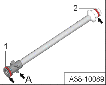
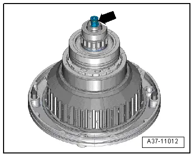
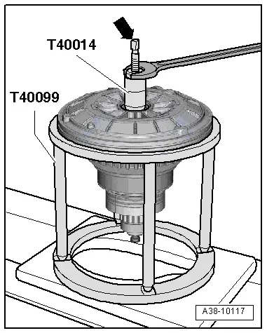
–  Press oil pipe -arrow- down into input shaft as far as stop.
l  
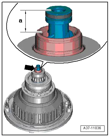
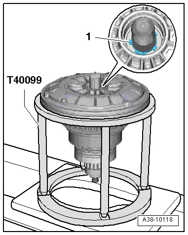
With oil pipe fully inserted, distance -a- from end of oil pipe to input shaft should be approx. 11.5 mm.
  Note
t  
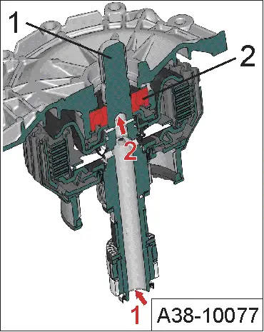
If the distance is less, the oil pipe may be damaged (the end could have broken off if the oil pipe was pushed in too far).
t  If the distance is larger, the oil pipe is not pushed in far enough.
  Caution
A damaged oil pipe will cause problems when driving off from a standstill or complete gearbox failure.
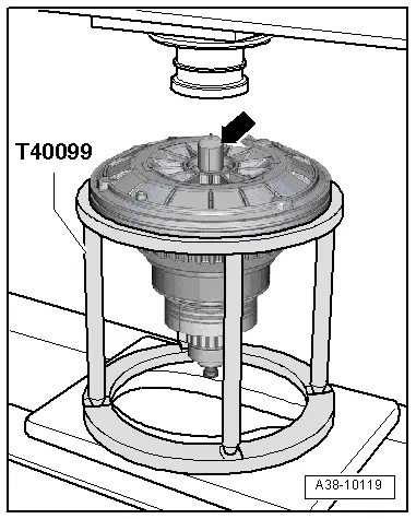
The input shaft must not be laid down on the projecting oil pipe -arrow-.
  A37-11036

Renewing ball bearing for input shaft > < Removing and installing input shaft