
A4 Mk3
| Dismantling and assembling input shaft |
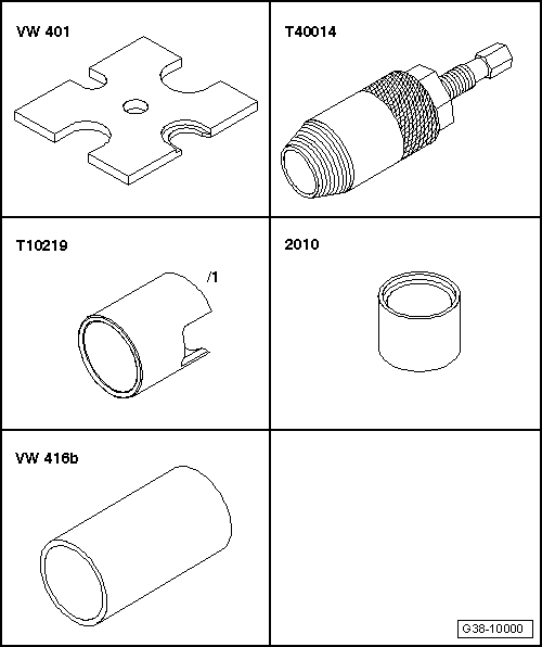
| Special tools and workshop equipment required |
| t | Thrust plate -VW 401- |
| t | Oil seal extractor -T40014- |
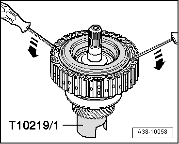
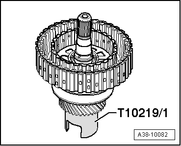
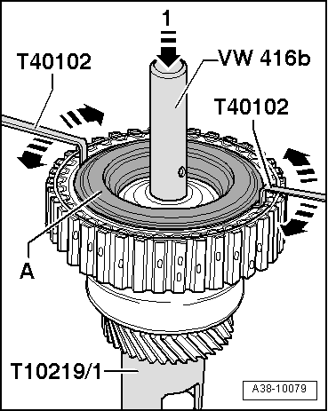
| t | Assembly tool -T10219/1- |
| t | Tube -2010- |
| t | Tube -VW 416 B- |
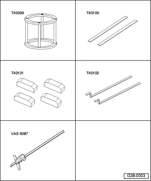
| t | Thrust piece -T40099- |
| t | 2x ruler -T40100- |
| t | Gauge block -T40101- |
| t | Feeler gauges -T40102- |
| t | Digital depth gauge -VAS 6087- |
| t | Protective gloves |
| t | Ice spray |
 Note
Note
|
|
|
|
|
 Caution
|
|
|
|
|
|
|
|
|
|
|
|
|
|
|
|
|
|