audi Workshop Repair Guides

Audi Workshop Service and Repair Manuals

Checking compression > < Cylinder head - exploded view
Removing and installing cylinder head
Removing
  Caution
To prevent irreparable damage to the electronic components when disconnecting the battery:
Observe notes on procedure for disconnecting the battery → Rep. gr.27.
–  Disconnect battery → Rep. gr.27.
–  Drain coolant → Chapter.
–  Remove air cleaner housing → Rep. gr.23.
–  Remove exhaust gas recirculation cooler → Chapter.
–  Remove turbocharger → Chapter.
–  Remove toothed belt → Chapter.
–  Remove cylinder head cover → Chapter.
–  Remove front exhaust pipe → Chapter.
   
–  Open hose clips -arrows- and detach air hose.
–  Detach guide tube for oil dipstick from throttle valve housing.
  A21-10302
  Caution
Observe rules for cleanliness when working on the fuel supply system.
–  Disconnect fuel supply hose -1- and fuel return hose -2-.
  A20-10427
–  Detach coolant hoses -3- and -4-.
  A10-11051
–  Detach hose clips -1- and -2- and remove coolant hose.
  A15-10661
–  Remove nut -3- for exhaust gas recirculation pipe.
–  Remove bolts -4- and -5-, move exhaust gas recirculation pipe aside.
–  Remove bolt on cylinder head for oil pressure pipe to turbocharger.
  Note
It is not possible to remove exhaust gas recirculation pipe.
  A26-10685
–  Remove bolt -4- and unclip air hoses for exhaust gas pressure sensor 1.
  A10-11053
–  Disconnect vacuum hose -2- on rear side of plenum chamber partition panel in direction of -arrow- and detach vacuum connection -1- from plenum chamber partition panel.
  A15-10662
–  Unplug the following electrical connectors:
3 - Variable intake manifold motor -V183-
4 - Intake manifold flap motor -V157-
5 - Exhaust gas recirculation valve -N18-
–  Remove camshaft toothed belt sprocket and use puller -T10052- to detach hub from camshaft.
–  Remove bolt securing toothed belt cover.
–  Remove nut securing toothed belt tensioning roller.
  A23-10264
–  Unscrew bolt for Hall sender -G40--arrow- and move Hall sender -G40- to one side.
  A23-0257
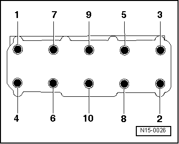
–  Remove cylinder head bolts in the sequence -1 ... 10-.
  Note
t  A second mechanic is required when removing the cylinder head.
t  The toothed belt tensioning roller is detached from the stud when the cylinder head is lifted out.
–  Lift cylinder head at gearbox end first and guide out of toothed belt cover. Make sure toothed belt tensioning roller does not drop out.
Installing
Install in reverse order. Note the following:
  Note
t  Always renew cylinder head bolts.
t  If repairing, carefully remove any remaining gasket material from the cylinder head and cylinder block. Ensure that no long scores or scratches are made on the surfaces. If using sandpaper, grain size must be at least 100.
t  Carefully remove any remaining emery and abrasive material.
t  
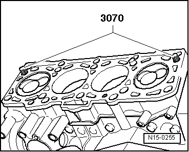
Do not remove new cylinder head gasket from packaging until it is ready to be fitted.
t  Handle gasket very carefully. Damage to the silicone coating or the indented area will lead to leaks.
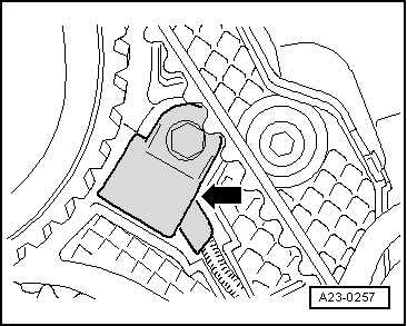
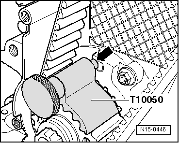
–  Before fitting cylinder head, remove crankshaft stop -T10050- and turn crankshaft in opposite direction of normal rotation until all pistons are almost evenly positioned below TDC.
–  Fit cylinder head gasket with marking facing upwards.
  N15-0026
–  To centralise, screw guide pins -3070- into outer holes on inlet side.
  Note
Position tensioning roller on dowel pin when fitting cylinder head.
–  Fit cylinder head, screw in 8 remaining cylinder head bolts and tighten by hand.
–  Unscrew guide pins through bolt holes in cylinder head using fitting tool from 3070 and install remaining cylinder head bolts.
–  Tighten cylinder head in four stages → Fig..
–  Secure toothed belt cover (rear) to cylinder head.
–  Install hub and camshaft sprocket.
–  Lock camshaft and high-pressure pump with diesel injection pump locking pin -3359-.
  N15-0255
–  Rotate crankshaft to TDC in direction of engine rotation and lock in position with crankshaft stop -T10050-.
–  Install toothed belt → Chapter.
The remaining installation steps are carried out in the reverse sequence. Note the following:
–  Install cylinder head cover → Chapter.
–  Install poly V-belt → Chapter.
–  Fill up with coolant → Chapter.
  N15-0446

Checking compression > < Cylinder head - exploded view