audi Workshop Repair Guides

Audi Workshop Service and Repair Manuals

Assembly mountings > < Securing engine to engine and gearbox support
Installing engine
Installing engine
Special tools and workshop equipment required
   
t  Assembly aid -T40169-
  W00-10593
t  Transport lock -T40170-
Tightening torques
  Note
t  Tightening torques apply only to lightly greased, oiled, phosphated or black-finished nuts and bolts.
t  Additional lubricants such as engine or gearbox oil may be used, but do not use lubricants containing graphite.
t  Do not use de-greased parts.
t  Tolerance for tightening torques: ± 15 %.
  W00-10594
ComponentNm
Bolts/nutsM69
M715
M820
M1040
M1265

Assembly mountings → Chapter „Assembly mountings - exploded view“.
   
Engine to manual gearbox
  A34-10493
ItemBoltNm
1 1)M10x50 2)65
2 3)M12x100 4)30 +90°
3 5), 6M12x75 4)30 +90°
4, 5 5)M12x120 4)30 +90°
7…9M10x75 4)15 +90°
10M12x50 4)30 +90°
ADowel sleeves for centralising
l  1) Also secures starter
l  2) Property class 10.9. The steel bolt may be re-used as often as necessary.
l  3) Also secures starter, with additional spacer sleeve between starter and gearbox
l  4) Bolts must not be used more often than twice → Anchor.
l  5) Also secures wiring retainer

   
t  
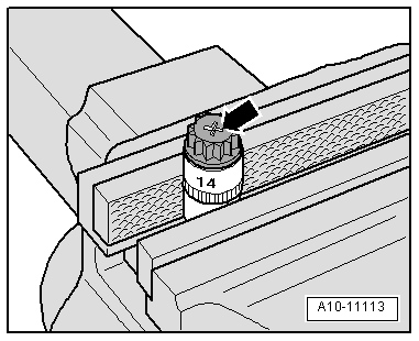
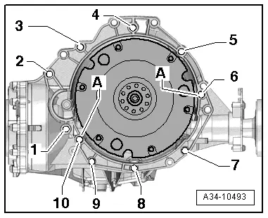
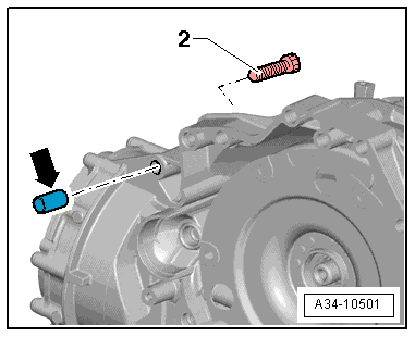
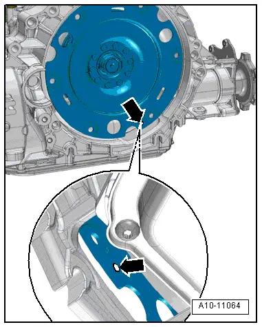
The aluminium bolts -2 … 10- must not be used more often than twice. After the first use, the bolts must therefore be identified with an „X“ made by two chisel marks -arrow-.
t  To avoid damaging the bolts when making this mark, do not clamp them directly in a vice. Clamp a 14 mm socket with 1/2" drive in a vice and insert the bolt as shown.
t  Bolts already marked with an „X“ must not be used again.
Procedure
  Note
t  Renew the bolts tightened with specified tightening angle.
t  Renew self-locking nuts and bolts as well as seals, gaskets and O-rings.
t  On vehicles with manual gearbox, a needle bearing must be fitted in the drive plate. Before installing, check whether a needle bearing is fitted. Press needle bearing into drive plate → Chapter.
t  Secure all hose connections with the correct type of hose clips (same as original equipment) → Electronic parts catalogue.
t  Fit all cable ties in the original positions when installing.
  A10-11113
–  The following preparations are required before joining engine and gearbox.
–  Insert assembly aid -T40169- into gearbox housing and dual-mass flywheel from below, as illustrated.
l  The assembly aid must engage in the semi-circular recess -1- and in the inspection hole -2-.
  Note
There is only one inspection hole on the circumference; turn the dual-mass flywheel accordingly.
–  Insert pin of assembly aid into hole on gearbox housing.
  A10-10825
–  Insert transport lock -T40170- into gearbox housing from below and clamp onto flange shaft -1-.
–  Check whether aluminium bolts securing engine to gearbox can be reused; if so, apply marking → Anchor.
  A10-10826
–  Check whether dowel sleeves -A- for centring engine and gearbox are fitted in cylinder block; install missing dowel sleeves.
–  Bring engine into position on gearbox, fit bolts -2 … 6- and tighten.
  Note
  A34-10493
t  Bolt -2- secures the starter to the gearbox and is provided with an additional spacer sleeve -arrow-.
t  The spacer sleeve must be fitted between starter and gearbox.
  A34-10501
–  Slacken spindle -10 - 222 A /11-.
–  Lower workshop hoist and place engine/gearbox assembly onto engine mountings.
–  Secure engine mounting → Chapter.
–  Detach workshop hoist -VAS 6100- and lifting tackle -2024 A-.
  A10-11059
–  Tighten bolts -1, 7, 8, 9, 10- securing engine to gearbox.
–  Remove transport lock -T40170- and assembly aid -T40169-.
  Note
  A34-10493
The following step is necessary to ensure that the clutch module is straight and that it makes even contact with the drive plate.
–  Install wheel housing liners → Rep. gr.66.
–  Fit front wheels → Wheels and tyres; Rep. gr.44.
–  Engage 4th gear and turn front wheels in direction of travel until clutch module is rotated by one complete turn (360°).
l  The inspection hole -arrow- should be visible again in the recess on the gearbox housing.
  A10-11064
–  Bolt clutch module onto drive plate as follows:
–  Hand-tighten first bolt -arrow- (2 Nm).
–  Turn front wheels in direction of travel until clutch module is rotated by 240°.
–  Tighten bolt accessible in this position to specified torque → Rep. gr.30.
–  Turn front wheels in direction of travel until clutch module is rotated by 120° each time and tighten remaining 2 bolts to specified torque → Rep. gr.30.
Remaining installation steps are carried out in reverse sequence; note the following:
–  Install particulate filter → Chapter.
–  Install pressure differential sender -G505- → Rep. gr.23.
–  Install alternator → Electrical system; Rep. gr.27.
–  Install power steering pump → Rep. gr.48.
–  Install air conditioner compressor → Rep. gr.87.
–  Install poly V-belt → Chapter.
–  Install cross member and torque reaction support → Chapter.
–  Install lock carrier and plenum chamber partition panel → Rep. gr.50.
–  Install air cleaner housing → Rep. gr.23.
–  Electrical connections and routing → Current flow diagrams, Electrical fault finding and Fitting locations.
–  Install engine control unit → Rep. gr.23.
–  Install electrical wiring, terminal 30 wiring junction 2 -TV22- and cover for electronics box in engine compartment → Electrical system; Rep. gr.97.
–  Install filler neck for washer fluid reservoir → Electrical system; Rep. gr.92.
–  Observe notes on procedure for connecting the battery → Electrical system; Rep. gr.27.
  Caution
Risk of irreparable damage to control units because of excessive voltage.
Never use battery charging equipment for boost starting.
–  Install air hoses with screw-type clips → Fig..
–  Check oil level → Booklet811 or → Booklet812.
–  Bleed fuel system → Rep. gr.23.
–  Connect coolant hoses with plug-in connector → Fig..
–  Fill up with coolant → Chapter.
  Note
t  Drained-off coolant may only be used again if the original cylinder head and cylinder block are re-installed.
t  Contaminated or dirty coolant must not be used again.
–  Install noise insulation panels → Rep. gr.66.
  A10-10629

Assembly mountings > < Securing engine to engine and gearbox support