
A4 Mk3
| Cylinder head - exploded view |
 Note
Note| The diagram shows the cylinder head on cylinder bank 2 (left-side). |
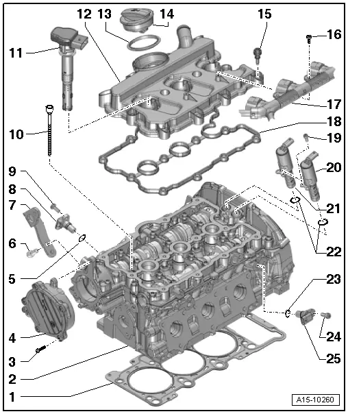
| 1 - | Cylinder head gasket |
| q | Renewing → Chapter „Removing and installing cylinder heads“ |
| q | Installation position: Part No. towards cylinder head |
| q | If renewed, change coolant and engine oil |
| 2 - | Cylinder head |
| q | Removing → Chapter |
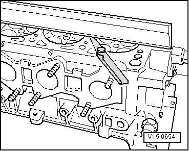
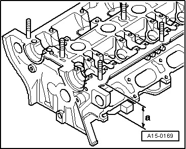
| q | → Fig. „Checking cylinder head for distortion“ |
| q | → Fig. „Cylinder head machining limit“ |
| q | Installing → Anchor |
| q | If renewed, change coolant and engine oil |
| 3 - | Bolt |
| q | Tightening torque → Rep. Gr.47 |
| 4 - | Exhauster pump |
| q | Removing and installing → Rep. Gr.47 |
| 5 - | O-ring |
| q | Renew |
| 6 - | Bolt |
| q | 20 Nm |
| 7 - | Engine lifting eye |
| 8 - | Hall sender for inlet camshaft |
| q | Cylinder bank 1 (right-side) Hall sender -G40- |
| q | Cylinder bank 2 (left-side) Hall sender 2 -G163- |
| 9 - | Bolt |
| q | 9 Nm |
| 10 - | Bolt |
| q | Procedure when loosening → Anchor. |
| q | Renew |
| q | Procedure when tightening → Anchor. |
| q | Tighten in three stages: |
| 1. | Tighten to 40 Nm |
| 2. | turn 90° further |
| 3. | turn 90° further |
| 11 - | Ignition coil |
| q | Remove with puller -T40039- |
| 12 - | Cylinder head cover |
| q | Removing and installing: left-side → Chapter, right-side → Chapter |
| 13 - | Seal |
| q | Renew if damaged or leaking |
| 14 - | Filler cap |
| 15 - | Bolt |
| q | Renew if seal is damaged |
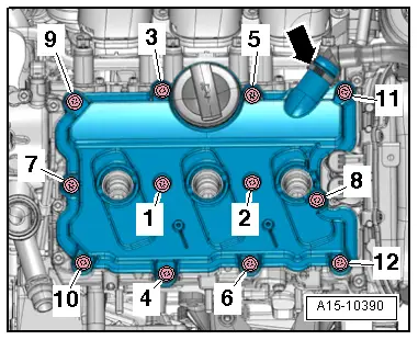
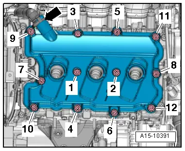
| q | Tightening torque → Fig. „Cylinder head cover (left-side) - tightening torque and sequence“ and → Fig. „Cylinder head cover (right-side) - tightening torque and sequence“ |
| 16 - | Bolt |
| q | Tightening torque → Rep. Gr.28 |
| 17 - | Connector console |
| q | For ignition coils |
| 18 - | Gasket for cylinder head cover |
| q | Renew if damaged or leaking |
| 19 - | Bolt |
| q | 2.5 Nm |
| 20 - | Solenoid valve for camshaft control (exhaust side) |
| q | Cylinder bank 1 (right-side) - exhaust camshaft control valve 1 -N318- |
| q | Cylinder bank 2 (left-side) - exhaust camshaft control valve 2 -N319- |
| 21 - | Solenoid valve for camshaft control (inlet side) |
| q | Cylinder bank 1 (right-side) camshaft control valve 1 -N205- |
| q | Cylinder bank 2 (left-side) - camshaft control valve 2 -N208- |
| 22 - | O-rings |
| q | Renew |
| 23 - | O-ring |
| q | Renew |
| 24 - | Bolt |
| q | 9 Nm |
| 25 - | Hall sender for exhaust camshaft |
| q | Cylinder bank 1 (right-side) Hall sender 3 -G300- |
| q | Cylinder bank 2 (left-side) Hall sender 4 -G301- |
|
|
|
|
|
|
|
|
|
|