
A4 Mk3
| Removing and installing chain for auxiliary drives |
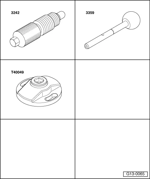
| Special tools and workshop equipment required |
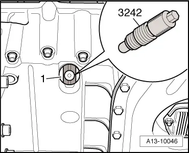
| t | Locking pin -3242- |
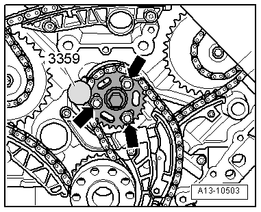
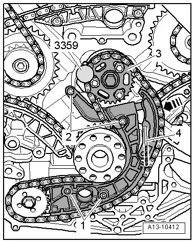
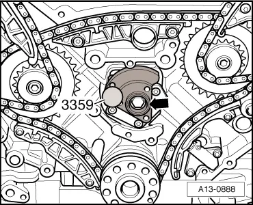
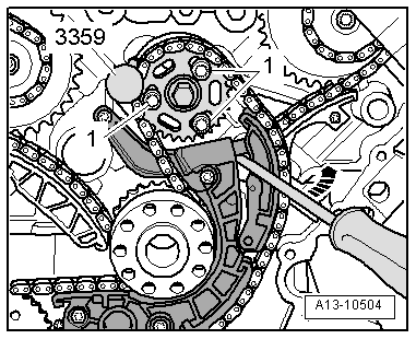
| t | Diesel injection pump locking pin -3359- |
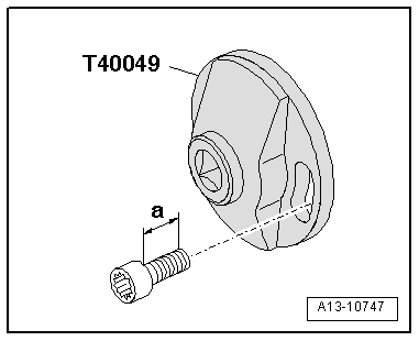
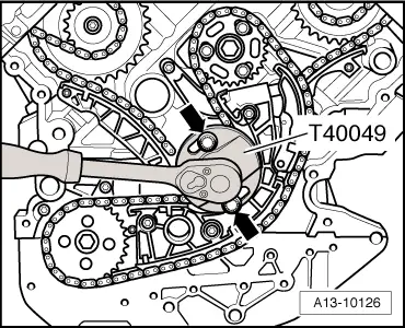
| t | Special wrench -T40049- |
| t | Nuts M12 (2x) |
| t | Drill bit, Ø 3.3 mm |
|
|
|
 Caution
|
|
|
|
|
|
|
|
|
|
|
|
|
|
 Note
Note
|
|
|
|
|
|