
A4 Mk3
| Cylinder head cover - exploded view |
 Note
Note| The diagram shows the cylinder head cover on cylinder bank 2 (left-side). |
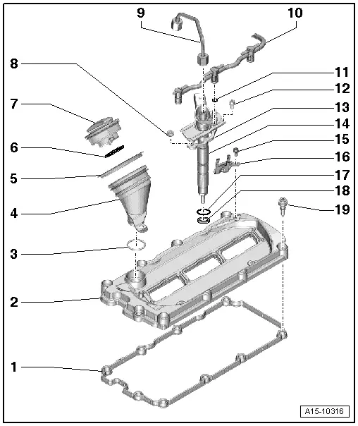
| 1 - | Gasket for cylinder head cover |
| q | Renew if damaged or leaking |
| 2 - | Cylinder head cover |
| q | Removing and installing: left-side → Chapter, right-side → Chapter |
| 3 - | O-ring |
| q | Renew |
| 4 - | Oil filler neck |
| q | To remove: Lift tab, turn oil filler neck anti-clockwise and take out |
| 5 - | Seal |
| 6 - | Seal |
| q | Renew if damaged or leaking |
| 7 - | Filler cap |
| 8 - | Nut |
| q | Tightening torque → Rep. gr.23 |
| 9 - | High-pressure pipe |
| q | Observe rules for cleanliness → Chapter |
| q | Mark allocation to injectors |
| q | Do not alter shape |
| q | Installing → Rep. gr.23 |
| 10 - | Fuel return line |
| q | Observe rules for cleanliness → Chapter |
| 11 - | O-ring |
| q | Renew |
| 12 - | Bolt |
| q | Tightening torque → Rep. gr.23 |
| 13 - | Clamping piece |
| q | Removing and installing → Rep. gr.23 |
| 14 - | Injector |
| q | Observe rules for cleanliness → Chapter |
| q | Removing and installing → Rep. gr.23 |
| 15 - | Bolt |
| q | 5 Nm |
| 16 - | Bracket |
| q | For electrical connector for Lambda probe -G39- |
| 17 - | O-ring |
| q | Renew |
| 18 - | Copper seal |
| q | Renew |
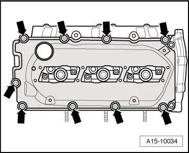
| 19 - | Bolt |
| q | With seal |
| q | Renew bolt if seal is damaged or leaking |
| q | Tightening torque and sequence → Fig. |
|
|