
A4 Mk3
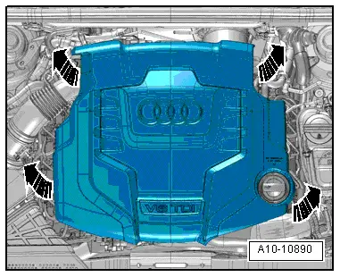
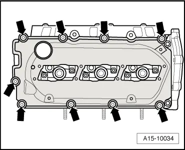
| Removing and installing cylinder head cover (left-side) |

| Special tools and workshop equipment required |
| t | Removal lever -80 - 200- |
| t | Open end spanner insert, AF 17 -V.A.G 1331/6- |
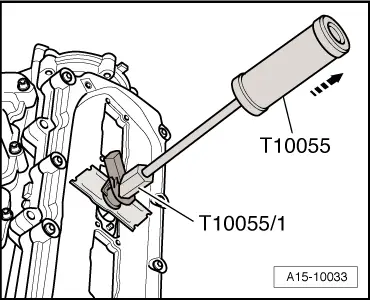
| t | Puller -T10055- with -T10055/1- |
| t | Socket -T40055- |
|
|
|
|
|
|
|
|
|
|
 Caution
|
|
|
|
|
|
|
|
|
|
|
|
|
|
 Note
Note
|
|