audi Workshop Repair Guides

Audi Workshop Service and Repair Manuals

Removing and installing intake manifold (bottom section) > < Fuel rail - exploded view
Removing and installing intake manifold (top section)
Special tools and workshop equipment required
   
t  Assembly tool -T10118-
  W00-1148
t  Hose clip pliers -V.A.G 1921-
  W00-0464
t  Socket Torx T30 -T10347-
Removing
  Note
t  In order to reach the injectors, first remove the intake manifold with the fuel rail.
t  The combustion chamber ring seal (teflon) and the O-ring must be renewed.
  WARNING
The fuel system is pressurised. The fuel pressure in the high-pressure part of the injection system must be reduced to a residual pressure prior to opening; for procedure see → Chapter.
–  Disconnect negative terminal from battery.
–  Remove engine cover panel.
  W00-10467
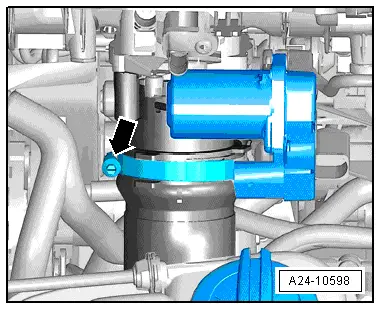
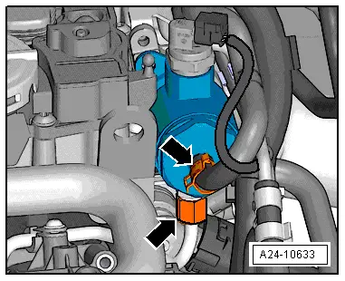
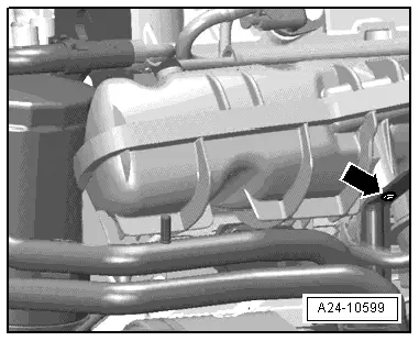
–  Disconnect vacuum line -arrow- leading to activated charcoal filter.
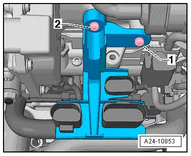
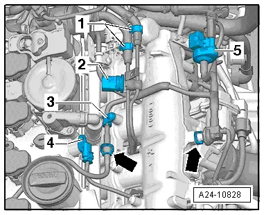
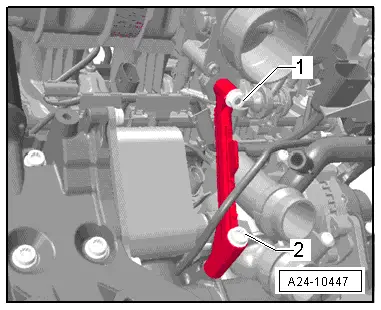
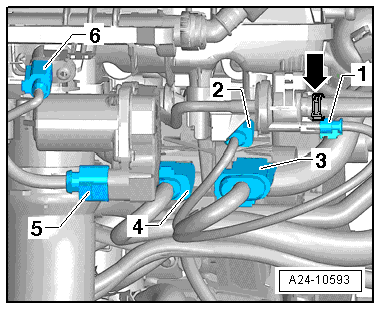
–  Unplug following electrical connectors:
1 - Activated charcoal filter solenoid valve 1 -N80-
2 - From knock sensor 1 -G61-
3 - From intake manifold flap valve -N316-, fuel pressure sender -G247- and Hall sender -G40-
4 - From injectors
5 - Throttle valve module -J338-
6 - Intake air temperature sender -G42-
  Note
t  The fuel system must not be under pressure.
t  Use a clean cloth to catch escaping fuel.
t  Seal off open connections with clean caps. It is essential to ensure that no dirt enters the fuel system.
  A24-10593
–  Unscrew bolts -1 and 2- and detach bracket for electrical connectors.
  A24-10853
–  Unplug electrical connector -2- at fuel pressure sender for low pressure -G410-.
–  Unplug electrical connector -4- at Hall sender -G40-.
–  Release hose clips -1- and disconnect the two fuel lines.
–  Release hose clip -3-.
  A24-10828
–  Detach line for active charcoal filter at intake manifold (top section) and at connection -arrows-.
–  Detach activated charcoal filter solenoid valve 1 -N80--5- from bracket.
–  Guide line coming from activated charcoal filter out underneath fuel lines and put to one side.
  A24-10828
–  Open hose clip -arrow- securing air hose and disconnect hose downwards from throttle valve module -J338-.
  A24-10598
–  Unscrew union nut for high-pressure fuel line -bottom arrow- at high-pressure pump.
–  Unscrew union nut and remove high-pressure fuel line from intake manifold (top section).
–  Loosen union nut securing high-pressure fuel line to fuel rail.
  A24-10633
–  Remove bolt -arrow- for coolant line from intake manifold (top section).
  A24-10599
–  Remove bolt -2-.
–  Unscrew bolts from intake manifold (top section) using socket -T10347-.
–  Detach top section from bottom section of intake manifold.
  A24-10447
–  Unplug electrical connector at cold-start valve -N17-.
  Note
Block off intake ports with a clean cloth.
–  Remove intake manifold (bottom section) → Chapter.
Installing
–  Renew connecting pieces for high-pressure fuel line at high-pressure fuel pump and at fuel rail.
–  Fit intake manifold onto studs (left and right) on cylinder head.
–  Tighten union nuts on high-pressure fuel line hand-tight.
–  Tighten intake manifold bolts to torque, working from inside to outside.
–  Secure high-pressure fuel line (specified torque).
–  The remaining installation steps are carried out in the reverse sequence.
l  Tightening torque: intake manifold - exploded view → Chapter
l  Tightening torque: fuel rail - exploded view → Chapter
  A24-10855

Removing and installing intake manifold (bottom section) > < Fuel rail - exploded view