audi Workshop Repair Guides

Audi Workshop Service and Repair Manuals

Removing and installing Hall senders > < Removing and installing ignition coils
Removing and installing knock sensors
   
Electrical connectors
1 - To injectors on cylinder bank 1
2 - Throttle valve module -J338-
3 - Knock sensor 1 -G61-
4 - Lambda probe -G39-
5 - Lambda probe after catalytic converter -G130-
  A28-10009
Electrical connectors
1 - Knock sensor 2 -G66-
2 - 
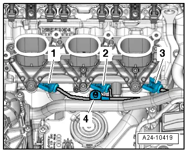
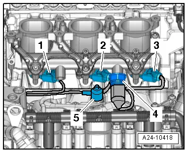
Injectors, cylinder bank 2, and for fuel pressure sender -G247-
Removing
  WARNING
t  The fuel system operates under high pressure. The pressure in the high-pressure part of the injection system must be reduced to a residual pressure prior to opening the system → Chapter.
t  A clean cloth must then be wrapped around the connection and the residual pressure dissipated by carefully loosening the connection.
t  Observe notes on procedure for disconnecting the battery → Rep. gr.27.
  A28-10020
Remove knock sensor on cylinder bank (right-side).
4 - Knock sensor 1 -G61-
  Note
To reach the bolt on knock sensor 1 -G61--4- you must first remove injector 2.
–  Remove intake manifold → Chapter.
–  Remove intake manifold (right-side, bottom section) with fuel rail → Chapter.
  A24-10419
Remove knock sensor on cylinder bank (left-side).
5 - Knock sensor 2 -G66-
  Note
To reach the bolt on knock sensor 2 -G66--5- you must first remove injector 5.
–  Remove intake manifold → Chapter.
–  Remove relevant intake manifold (bottom section) with fuel rail → Chapter.
Installing
–  Re-install whichever knock sensor was removed.
  Note
The tightening torque influences the function of the knock sensor.
t  Tightening torque: refer to exploded view of ignition system → Chapter.
–  Install relevant intake manifold (bottom section) with fuel rail → Chapter.
–  Install intake manifold → Chapter.
  A24-10418

Removing and installing Hall senders > < Removing and installing ignition coils