
A4 Mk3
| Overview of fitting locations |
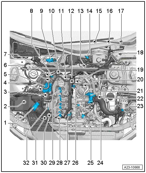
| 1 - | Air mass meter -G70- |
| q | Removing and installing → Chapter |
| 2 - | Air filter bypass flap valve -N275- |
| q | Country-specific version |
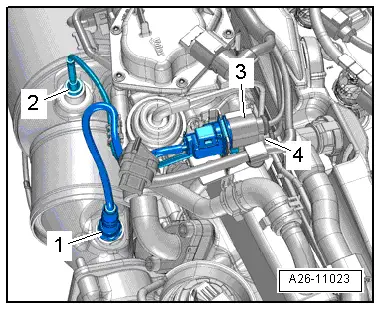
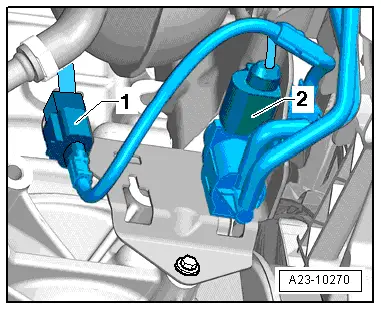
| 3 - | Electrical connectors |
| q | For Lambda probe -G39- |
| q | For exhaust gas temperature sender 3 -G495- |
| q | Fitting location → Fig. |
| 4 - | Lambda probe -G39- with Lambda probe heater -Z19- |
| q | Fitting location → Fig. |
| q | Exploded view → Chapter |
| 5 - | Exhaust gas recirculation control motor -V338- with exhaust gas recirculation potentiometer -G212- |
| q | Integrated into exhaust gas recirculation cooler |
| q | Removing and installing exhaust gas recirculation cooler → Rep. gr.26 |
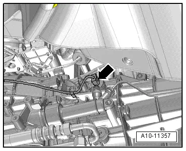
| 6 - | Exhaust gas temperature sender 3 -G495- |
| q | Fitting location → Fig. |
| q | Exploded view → Chapter |
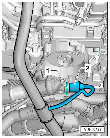
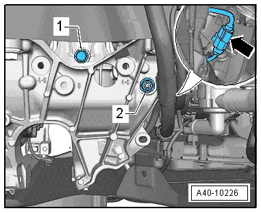
| 7 - | Radiator outlet coolant temperature sender -G83- |
| q | Fitting location → Fig. |
| 8 - | Pressure differential sender -G505- |
| q | Fitting location → Fig. |
| q | Exploded view → Chapter |
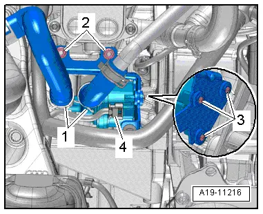
| 9 - | Coolant circulation pump -V50- |
| q | Vehicles with start/stop system only |
| q | Removing and installing → Rep. gr.19 |
| 10 - | Exhaust gas temperature sender 4 -G648- |
| q | Exploded view → Chapter |
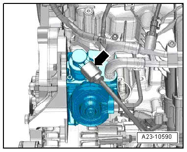
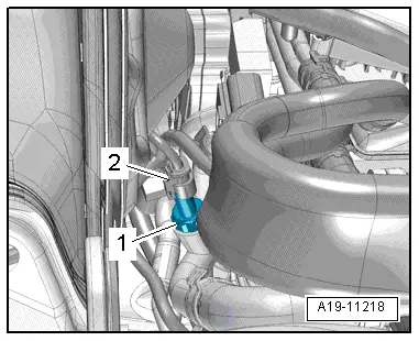
| 11 - | Coolant temperature sender -G62- |
| q | Fitting location → Fig. |
| q | Removing and installing → Rep. gr.19 |
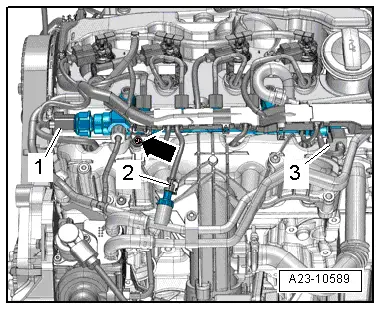
| 12 - | Fuel pressure regulating valve -N276- |
| q | Fitting location → Fig. |
| q | Removing and installing → Chapter |
| 13 - | Gearbox neutral position sender -G701- |
| q | Vehicles with start/stop system only |
| q | Fitting location → Fig. |
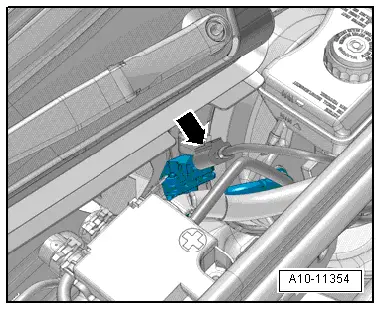
| 14 - | Brake servo pressure sensor -G294- |
| q | Fitting location → Fig. |
| 15 - | Accelerator position sender -G79- and accelerator position sender 2 -G185- |
| q | Fitting location → Fig. |
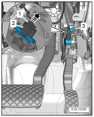
| 16 - | Brake light switch -F- and brake pedal switch -F47- |
| q | Fitting location → Fig. |
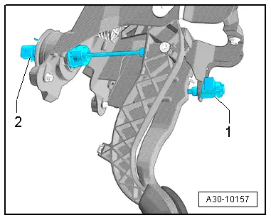
| 17 - | Clutch position sender -G476- |
| q | With clutch pedal switch for engine start -F194- and clutch pedal switch -F36- |
| q | Only on vehicles with manual gearbox |
| q | Fitting location → Fig. |
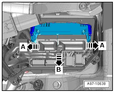
| 18 - | Engine control unit -J623- |
| q | Fitting location → Fig. |
| q | Removing and installing → Chapter |
| 19 - | Engine speed sender -G28- |
| q | Fitting location → Fig. |
| q | Exploded view → Chapter |
| 20 - | Pump for exhaust gas recirculation cooler -V400- |
| q | Fitting location → Fig. |
| 21 - | Throttle valve module -J338- with throttle valve potentiometer -G69- |
| q | Exploded view → Chapter |
| 22 - | Left electrohydraulic engine mounting solenoid valve -N144- |
| q | On left side only |
| q | Fitting location → Fig. |
| 23 - | Charge pressure sender -G31-/intake air temperature sender -G42- |
| q | Fitting location → Fig. |
| 24 - | Fuel temperature sender -G81- |
| q | Fitting location → Fig. |
| 25 - | Fuel metering valve -N290- |
| q | Fitting location → Fig. |
| q | Removing and installing → Chapter |
| 26 - | Glow plugs |
| q | Glow plug 1 -Q10- |
| q | Glow plug 2 -Q11- |
| q | Glow plug 3 -Q12- |
| q | Glow plug 4 -Q13- |
| q | Removing and installing → Chapter |
| 27 - | Fuel pressure sender -G247- |
| q | Fitting location → Fig. |
| q | Removing and installing → Chapter |
| 28 - | Hall sender -G40- |
| q | Fitting location → Fig. |
| q | Removing and installing → Chapter |
| 29 - | Injectors |
| q | Injector, cylinder 1 -N30- |
| q | Injector, cylinder 2 -N31- |
| q | Injector, cylinder 3 -N32- |
| q | Injector, cylinder 4 -N33- |
| q | Removing and installing → Chapter |
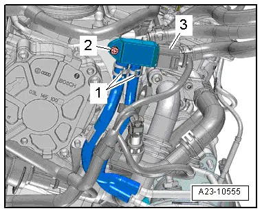
| 30 - | Charge pressure control solenoid valve -N75- |
| q | Fitting location → Fig. |
| 31 - | Exhaust gas recirculation cooler change-over valve -N345- |
| q | Electrical connector → Fig. |
| 32 - | Position sender for charge pressure positioner -G581- |
| q | Fitting location → Fig. |
|
|
 Note
Note
|
|
|
|
|
|
|
|
|
|
|
|
|
|
|
|
|
|
|
|
|
|
|
|
|
|
|
|
|
|
|
|
|
|